


23
BACK
L
L
R
BACK
R
R
L
CAUTION:SPEAKER IMPEDANCE
6 OHMS MIN. PER EACH
SPEAKER TERMINAL
SURROUND
(
SURR
)
SPEAKERS
AC
INLET
AM
ANT.
FM
ANT.
75
MULTI
CHANNEL
INPUT
RS 232
GND
FRONT
SPEAKERS
CENTER
SPEAKER
CAUTION:
SPEAKER IMPEDANCE
6 OHMS MIN. PER EACH
SPEAKER TERMINAL
MODEL NO. TX-DS989
AV RECEIVER
VIDEO
S VIDEO
DVD
VIDEO
5
VIDEO
4
VIDEO
3
MONITOR
OUT
VIDEO
1
VIDEO
2
OUT
IN
IN
IN
IN
IN
IN
OUT
R
L
VIDEO
S VIDEO
C
D
TAPE
2
TAPE
1
I
N
I
N
I
N
I
N
OUT
OUT
L
R
PHONO
3
2
1
3
2
5
4
1
DIGITAL
OUTPUT
(
COAXIAL
)
AC-3
RF
DIGITAL
INPUT
(
COAXIAL
)
DIGITAL
OUTPUT
(
OPTICAL
)
DIGITAL
INPUT
(
OPTICAL
)
INPUT 2
P
B PRY
INPUT 3
PB PRY
OUTPUT
PB PRY
COMPONENT
VIDEO
INPUT 1
P
B PRY
1
2
IR IN
MAIN ZONE 2
ZONE 2
R
L
OUT
C
FRONT
AMP
IN
R
L
SURR
BACK
SURR
PRE OUT
SUB
WOOFER
1
2
AC OUTLETS
AC 230V 50Hz
SWITCHED
TOTAL 120W MAX.
AM
FM
75
ANTENNA
BACK
L
L
R
BACK
R
R
L
CAUTION:SPEAKER IMPEDANCE
6 OHMS MIN. PER EACH
SPEAKER TERMINAL
SURROUND
(
SURR
)
SPEAKERS
AC
INLET
AM
ANT.
FM
ANT.
75
MULTI
CHANNEL
INPUT
RS 232
GND
FRONT
SPEAKERS
CENTER
SPEAKER
CAUTION:
SPEAKER IMPEDANCE
6 OHMS MIN. PER EACH
SPEAKER TERMINAL
MODEL NO.
TX-DS989
AV RECEIVER
VIDEO
S VIDEO
DVD
VIDEO
5
VIDEO
4
VIDEO
3
MONITOR
OUT
VIDEO
1
VIDEO
2
OUT
IN
IN
IN
IN
IN
IN
OUT
R
L
VIDEO
S VIDEO
C
D
TAPE
2
TAPE
1
I
N
I
N
I
N
I
N
OUT
OUT
L
R
PHONO
3
2
1
3
2
5
4
1
DIGITAL
OUTPUT
(
COAXIAL
)
AC-3
RF
DIGITAL
INPUT
(
COAXIAL
)
DIGITAL
OUTPUT
(
OPTICAL
)
DIGITAL
INPUT
(
OPTICAL
)
INPUT 2
P
B
P
R
Y
INPUT 3
P
B
P
R
Y
OUTPUT
P
B
P
R
Y
COMPONENT
VIDEO
INPUT 1
P
B
P
R
Y
1
2
IR IN
MAIN ZONE 2
ZONE 2
R
L
OUT
C
FRONT
AMP
IN
R
L
SURR
BACK
SURR
PRE OUT
SUB
WOOFER
1
2
AC OUTLETS
AC 230V 50Hz
SWITCHED
TOTAL 120W MAX.
AM
FM
75
ANTENNA
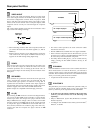
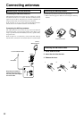
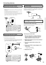
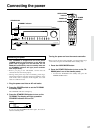
Connecting antennas
Connecting the antenna cable to the 75/300 Ω
antenna adapter (not included)
Connecting the 300 Ω ribbon wire:
Loosen the screws and wrap the wire around these screws. Then
tighten the screws with a screwdriver.
Connecting the coaxial cable:
1. With your fingernail, or a small screwdriver,
press the stoppers of the 75/300 Ω antenna
adapter outward and remove the cover.
2. Remove the transformer wire A from slit B and
insert it into slit C.
3. Prepare the coaxial cable as shown in the
diagram.
4. Connect the 75/300 Ω antenna adapter to the
coaxial cable.
1 Insert the end of the cable.
2 Clamp it in place with pliers.
5. Reinstall the cover.
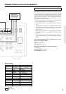
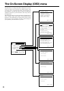
Directional linkage
Do not use the same antenna for both FM and TV (or VCR)
reception since the FM and TV (or VCR) signals can interfere with
each other. If you must use a common FM/TV (or VCR) antenna,
use a directional linkage type splitter.
Outdoor
antenna
300 Ω
ribbon wire
To TV (or VCR)To receiver
1 2 3, 4
✦
✦
✦
✦
✦
✦
✦
✦
✦
✦
✦
6
mm
3
mm
6
mm
15mm
Slit B
Wire A
Slit C
Outdoor antenna
(Indoor)
AM loop antenna
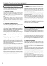
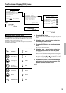
Connecting an FM outdoor antenna
Please make sure that you follow the considerations:
• Keep the antenna away from noise sources (neon signs, busy
roads, etc.).
• It is dangerous to put the antenna close to power lines. Keep it
well away from power lines, transformers, etc.
• To avoid the risk of lightning and electrical shock, grounding
is necessary. Follow item 14 of the “Important Safeguards” on
page 2 when you install the outdoor antenna.
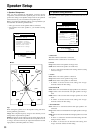
Connecting an AM outdoor antenna
An outdoor antenna will be more effective if it is stretched
horizontally above a window or outside.
• Do not remove the AM loop antenna.
• To avoid the risk of lightning and electrical shock, grounding
is necessary. Follow item 14 of the “Important Safeguards” on
page 2 when you install the outdoor antenna.