


13
R
L
FRONT
SPEAKERS
CENTER
SPEAKER
CAUTION:
SPEAKER IMPEDANCE
6 OHMS MIN. PER EACH
SPEAKER TERMINAL
MODEL NO.
TX-DS989
AV RECEIVER
INPUT 2
P
B
P
R
Y
INPUT 3
P
B
P
R
Y
OUTPUT
P
B
P
R
Y
IR IN
MAIN ZONE 2
AC
INLET
AC OUTLETS
AC 120V 60Hz
SWITCHED
TOTAL 120W 1A MAX.
AC OUTLETS
AC 120V 60Hz
SWITCHED
TOTAL 120W 1A MAX.
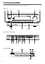
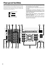
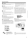
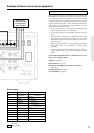
Rear panel facilities
ANTENNA
These jacks are for connecting the FM indoor antenna and AM
loop antenna that are supplied with the TX-DS989.
AMP IN
These jacks are for connecting a graphic equalizer for further
control of the audio output.
• When connecting a graphic equalizer, remove the attached
jumper plugs and store them carefully so as not to lose them.
• Only remove the jumper plugs when required. After you finish
using an AMP IN jack, replace the jumper plug.
PRE OUT
These jacks are for connecting auxiliary power amplifiers.
• When connecting auxiliary power amplifiers, remove the
attached jumper plugs and store them carefully so as not to
lose them.
• Only remove the jumper plugs when required. After you finish
using a PRE OUT jack, replace the jumper plug.
MONITOR OUT
There are 2 monitor outputs and each one includes both composite
video and S-video configurations. When connecting two video
monitors or televisions, be aware that the OSD interface can only
be used with MONITOR OUT 1 (OSD will not be displayed on the
video monitor connected to MONITOR OUT 2).
DIGITAL INPUT/OUTPUT
(coaxial, optical, and input-only AC-3RF)
These are the digital audio inputs and outputs. There are 5 digital
inputs with coaxial jacks, 3 with optical jacks, and 1 AC-3RF
input. The inputs accept digital audio signals from a compact disc,
LD, DVD, or other digital source component. For digital output,
there is 1 coaxial output and 1 optical output. The digital outputs
can be connected to MD recorders, CD recorders, DAT decks, or
other similar components.
• When using the digital inputs and outputs, make sure to also
connect the analog connections whenever possible.
• When using one of the optical input or output jacks, remove
the protective cap and keep it safely. When the jack is not used,
replace the protective cap.
• When using an optical input or output jack, always use an
optical fiber cable.
COMPONENT VIDEO INPUT/OUTPUT
If your DVD player or other device has component video
connectors, be sure to connect them to these component video
connectors on the TX-DS989. The TX-DS989 has three
component video input connectors to obtain the color information
(Y, P
B, PR) directly from the recorded DVD signal or other video
component and one component video output connector to output it
directly into the matrix decoder of the display device. By sending
the pure DVD component video signal directly, the DVD signal
forgoes the extra processing that normally would degrade the
image. The result is vastly increased image quality, with
incredibly lifelike colors and crisp detail.
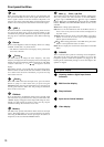
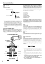
Optical digital input terminal
An optical digital input terminal is
equipped with a protection cap. When
connecting, remove this cap. When
not using, put the cap back on the
terminal.
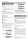
AC OUTLETS
The TX-DS989 is supplied with two AC mains outlets for
connecting the power cords from other devices so that their power
is supplied through the TX-DS989. By doing this, you can use the
STANDBY/ON button on the TX-DS989 to turn on and off the
connected devices as well.
Caution
Make sure that the total capacity of the other components
connected to this unit does not exceed the capacity that is printed
on the rear panel. For the North American model, the capacity is
120 watts.
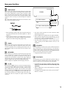
YPB PR RCA type
U.S. and Canadian
models
COAXIAL Coaxial cable
AC-3RF Coaxial cable
OPTICAL Optical fiber cable