


8
Front & Rear Panels
—Continued
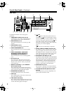
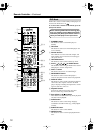
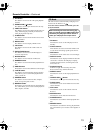
Rear Panel
For detailed information, refer to the pages in
parenthesis.
A
COMPONENT VIDEO (20–23, 25, 26)
A DVD player, TV, or other component that sup-
ports component video can be connected here.
B
AM ANTENNA (18, 19)
These push terminals are for connecting an AM
antenna.
C
FM ANTENNA (18, 19)
This socket is for connecting an FM antenna.
D
FRONT SPEAKERS B (17)
These terminal posts are for connecting speaker
set B.
E
FRONT SPEAKERS A, SURROUND
SPEAKERS, CENTER SPEAKER &
SURROUND BACK SPEAKER (17)
These terminal posts are for connecting speaker
set A.
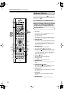
F
AC OUTLET (30)
This switched AC outlet can be used to supply
power to another component. The connector type
depends on the country in which you purchased
your AV Receiver.
G
DIGITAL IN OPTICAL 1, 2, 3 & COAXIAL
(20–23, 25, 26, 28, 29)
These optical and coaxial sockets can be used to
connect a CD, DVD, or LD (laser disc) player and
other components with digital audio outputs.
H
SUBWOOFER PRE OUT (17)
A powered subwoofer can be connected here.
I
CD IN (28)
These analog inputs can be used to connect a CD
player with analog outputs.
J
TAPE IN/OUT (28, 29, 33)
These analog inputs and outputs can be used to con-
nect a cassette recorder, Mini Disc recorder, or other
recorder with analog inputs and outputs.
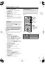
K
(30)
This (Remote Interactive) socket can be con-
nected to the socket on another Onkyo compo-
nent. The AV Receiver’s remote controller can then
be used to control that component. To use , you
must make an analog audio connection (RCA)
between the AV Receiver and the other component,
even if they are connected digitally.
Note:
can only be used with Onkyo components.
L
VIDEO 1 IN/OUT & VIDEO 2 IN (24, 25, 45)
The VIDEO 1 S-Video, composite video, and audio
inputs and outputs can be used to connect a VCR.
The VIDEO 2 S-Video, composite video, and audio
inputs can be used to connect another video source
(e.g., cable TV, satellite TV, or a set-top box).
M
DVD IN/MULTI CH INPUT (23, 24)
The FRONT, SURR, CENTER, and SUBWOOFER
inputs can be used to connect components with mul-
tiple analog audio outputs, including DVD players
with individual 5.1-channel analog outputs. The
S-Video or composite video input should be con-
nected to a video output on the DVD player.
N
MONITOR OUT (21, 22)
The S-Video or composite video output should be
connected to a video input on your TV or projector.
O
VOLTAGE SELECTOR (Worldwide model
only) (9)
This voltage selector provides compatibility with
power systems around the world.
L
R
ANTENNA
FM
75
AM
120
V
VOLTAGE
SELECTOR
220
-
230
V
SWITCHED
100W MAX.
AC OUTLET
OPTICAL COAXIAL
123
DIGITAL
IN
VIDEO 1
/2/3IN
R
L
SURROUND
SPEAKERS
CENTER
SPEAKER
SURROUND BACK
SPEAKER
REMOTE
CONTROL
IN
IN
IN
IN
IN
IN
IN
FRONT
SURR
CENTER
SUB
WOOFER
OUT
OUT
OUT
VIDEO 2
VIDEO 1
DVD MONITOR
OUT
VIDEO
S VIDEO
DVD
TAPE
CD
L
R
VIDEO 2
VIDEO 1
SUBWOOFER
PRE OUT
DVD
IN
COMPONENT VIDEO
Y
P
B
PR
OUT
L
R
R
L
FRONT
SPEAKERS A
R
L
FRONT
SPEAKERS B
Class 2 Wiring
16
789JK M N O
4532
L