


14
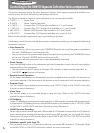
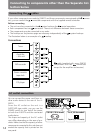
Connecting the cables
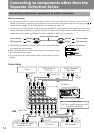
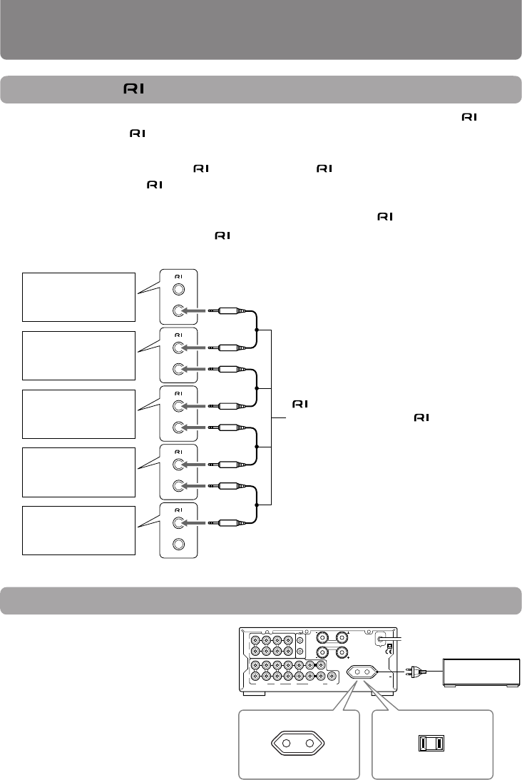
If your other components are made by ONKYO and those components are equipped with connec-
tors, you can control the
-connected components with the supplied remote controller.
Before connecting
• The unit must be connected in the
system hookups for control operations.
• Each component has two
connectors. There is no difference between these connectors.
• The components may be connected in any order.
• The hookups on the previous page are necessary independently of the
system hookups.
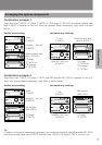
The illustration below is an example of a
hookup.
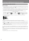
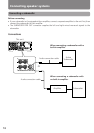
Connections
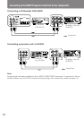
AC outlet connection
You can connect the power cord from an-
other audio device to the rear of the A-
905TX.
Since the AC outlet on the unit is a
SWITCHED type outlet, you can use the
POWER switch to turn on/off the power
to both the A-905TX and the connected
audio device.
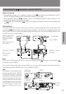
The shape and capacity of the AC outlet
may differ depending on the area of pur-
chase. Make sure that the capacity of other
components connected to this unit does not
exceed the capacity that is printed on the
rear panel.
cable (supplied with every ONKYO
component that has
connectors
except for the amplifier and receiver)
MD recorder
Tuner
Stereo cassette
tape deck
Amplifier
– this unit
CD player
L
R
L
R
LINE/DVDTUNER
OUT
IN
L
R
TAPE
SPEAKERS
OUT
(
REC
)
OUT
(
REC
)
IN
(
PLAY
)
IN
(
PLAY
)
OUT
(
REC
)
IN
(
PLAY
)
REMOTE
CONTROL
CD
CDR/PC
PROCESSOR
MD
SUBWOOFER
PRE OUT
L
R
AC OUTLET
AC 230-240V
50Hz
SWITCHED
100W MAX.
CAUTION:
SPEAKER IMPEDANCE
4 OHMS MIN./SPEAKER
Capacity is 120 watts.
120 V, 60 Hz models
230-240 V, 50 Hz models
Capacity is 100 watts.
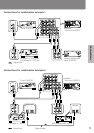
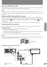
Connecting to components other than the Separate Col-
lection Series