


12
Connecting to components other than the
Separate Collection Series
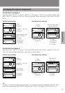
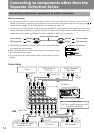
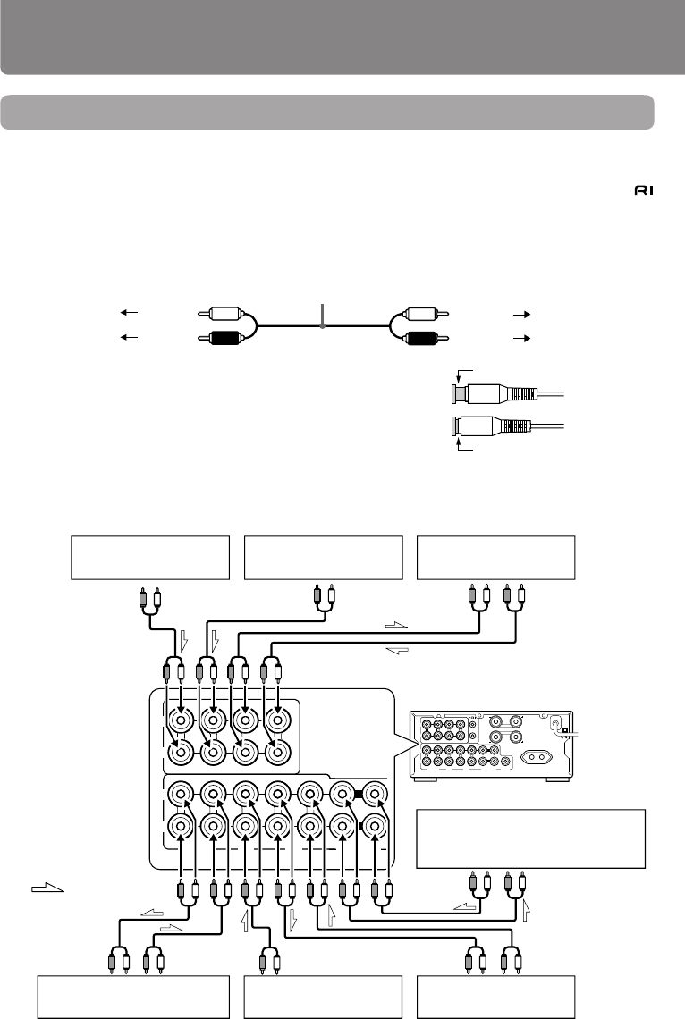
Connecting audio/video equipment to audio connectors
Before connecting
• Do not connect the AC power cord (mains lead) to the wall outlet (the mains) until you have com-
pleted all the other connections including the sound processor connections on the next page, the
connections on page 14, and the speaker connections on page 15.
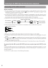
• On each pair of connectors, a red connector (marked R) corresponds to the right channel, and a
white connector (marked L) to the left channel.Connect white plugs of audio connection cables to L
connectors and connect red plugs of audio connection cables to R connectors .
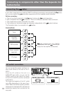
Improper connection
Insert completely
• Please refer to the instruction manual for each component when
you make any connections.
• Insert the plug securely. If the connection is incomplete, noise
or malfunction may result.
• If you are using an audio optical cable, do not bend or wrap it
tightly.
Connections
L
R
L
R
LINE/DVDTUNER
OUT
IN
L
R
TAPE
SPEAKERS
OUT
(
REC
)
OUT
(
REC
)
IN
(
PLAY
)
IN
(
PLAY
)
OUT
(
REC
)
IN
(
PLAY
)
REMOTE
CONTROL
CD
CDR/PC
PROCESSOR
MD
SUBWOOFER
PRE OUT
L
R
AC OUTLET
AC 230-240V
50Hz
SWITCHED
100W MAX.
CAUTION:
SPEAKER IMPEDANCE
4 OHMS MIN./SPEAKER
L
R
L
R
OUT
(
REC
)
OUT
(
REC
)
IN
(
PLAY
)
IN
(
PLAY
)
OUT
(
REC
)
IN
(
PLAY
)
L
R
CD
CDR/PC
MD
LINE/DVDTUNER
TAPE
OUT
IN
PROCESSOR
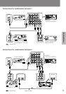
Audio connection cable
To L connector (White)
To R connector
(Red)
(White) To L connector
(Red)
To R connector
DVD player or
VCR, etc.
Stereo cassette
tape deck
PLAY
OUTPUT
REC
INPUT
AUDIO OUT
AUDIO
OUT
OUTPUT
REC
INPUT
PLAY
OUTPUT
OUTPUT
: Signal flow
CD recorder or audio
processor for PC
CD player
MD recorder
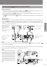
Amplifier
– this unit (A-905TX)
Tuner
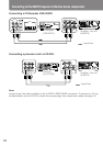
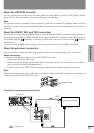
(illustration is 230-240 V model)
Sound processor
(such as a signal processor and
a graphic equalizer)