


9
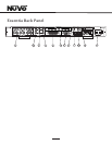
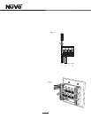
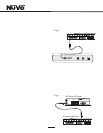
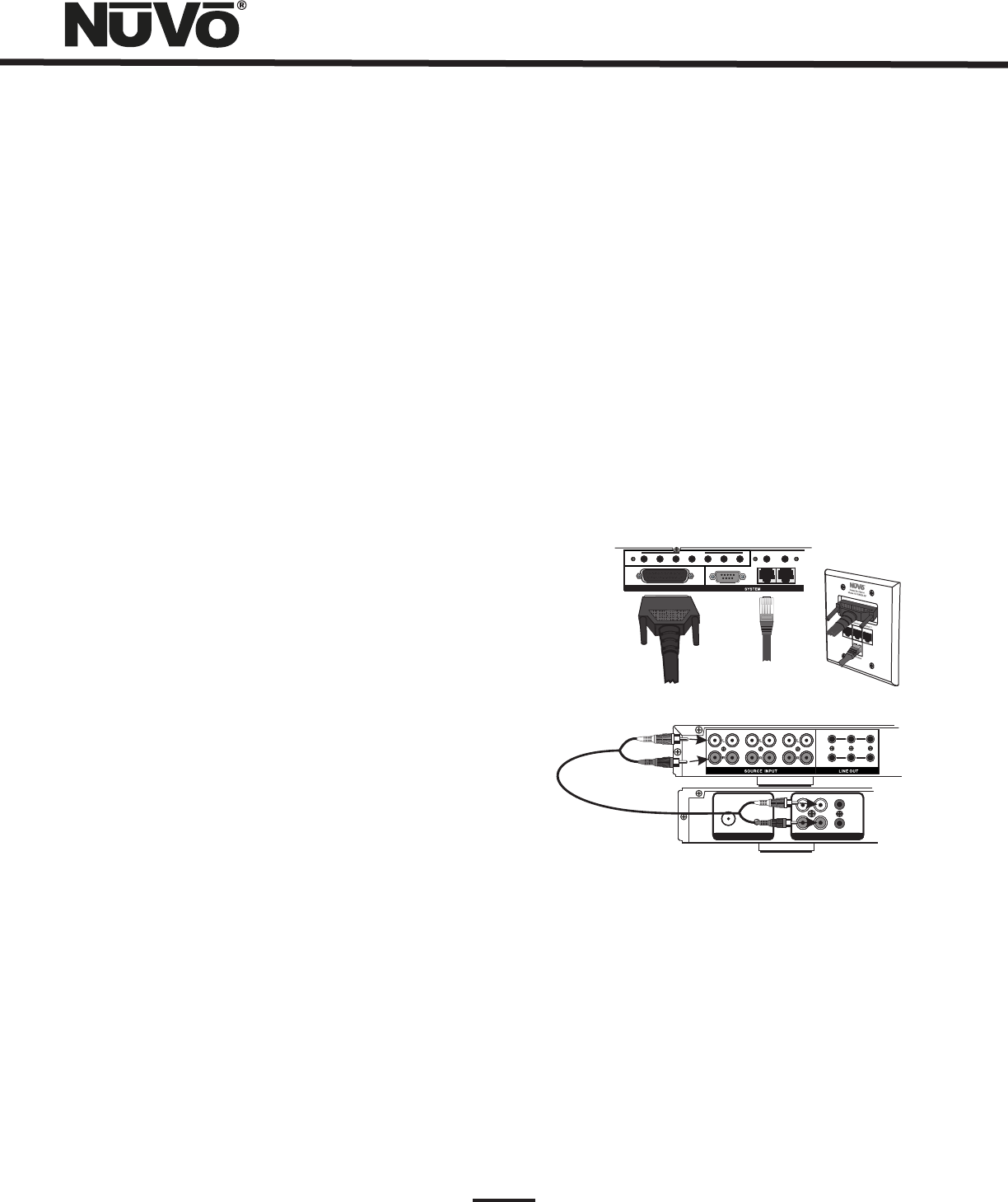
V. Connecting the Allport to the Essentia Amplifier (Fig. 4)
Once installed, the front of the Allport has three Device
RJ45 jacks for CAT5 connections from the NuVoNet Suite
components, and an RJ45 jack labeled NuVoNet which
must be connected to the NuVoNet input on the back of
the Essentia amplifier. This is necessary for Control Pad
communication, regardless the use of the NuVoNet Suite
components. Once connected, the Control Pads are ready to
communicate with the System. The Essentia System is
shipped with a six-foot pre-terminated CAT5 network cable,
or you can purchase one if a different length is required.
The speaker connection is made with the 25-pin Allport
Cable. The modular speaker connectors must be plugged into
the appropriate speaker connections on the back of the
Allport.
Fig. 4
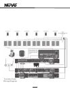
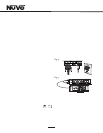
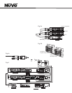
VI. Attaching Audio Source Equipment (Fig. 5)
Each piece of audio equipment is connected to the Essentia
amplifier with standard stereo RCA cables. Attach an RCA
cable to the corresponding audio output on the source
equipment and to the desired source input on the back of
the Essentia amplifier. The numbered input for each source
is important in the configuration of the system. This will be
covered in detail in the Essentia Configurator portion of this
manual.
Using the Fixed and Variable Lineouts
The Zone 1 and 2 outputs have 3.5mm stereo pre-amp
lineouts attached to them. Their purpose is to provide the
zone s current audio selection signal to an additional
amplifier. Both versions, fixed (a constant signal that
requires a volume control separate from the NuVo zone
Control Pad) and variable (a signal that varies in level
relative to the volume setting on the NuVo zone Control Pad)
are both simultaneously active and require no external
switch for use.
Each output has an attached voltage trigger output that
allows the attached amplifier to be triggered from a voltage
presented when the zone Control Pad is turned on. The
TUNE R BA NTENN A INPUT
IN
USE ONLY Nu Vo
NV-T2PA S
POWER ED ANTEN NA SYST EM
L
AUDIO O UT
AUX IN
R
TRIGG ER
ON=+1 2V
AUDIO
OUTPU T
FIX ED VAR
ZON E
7
TRI G
ZON E
8
7 8 9 10 11 12
Fig. 5
T2G AM/FM and XM Tuners
Each of the T2G Tuner components houses two individual
AM/FM or Satellite receivers, which have their own display
on the front panel. Once the T2G is plugged in and the
NuVoNet CAT5 is connected to the Allport, the initial display,
OPERATING MODE will appear for each tuner. Below this, the
choices are STAND ALONE, SOURCE 6, SOURCE 5, SOURCE 4,
SOURCE 3, SOURCE 2, and SOURCE 1. Stand Alone is
automatically highlighted at initial startup. Selecting the
appropriate Essentia source input is accomplished by
turning the Select knob for each tuner counter-clockwise
until the desired source input number is highlighted. It is
selected by pushing the Select knob. Once this is complete,
the Essentia System NuVoNet will recognize that source.
STATUS
NuVoN et
RS2 32
1
SUM
ALL PORT CONNECTION
IR OUTPU TS
2 3 4 5 6
LIN K
MUT E
ALL PORT CONNECTION
Setting up NuVo Sources for use with NuVoNet
A feature of the Essentia System is its ability to
automatically communicate with the T2G family of tuners,
the M3 Audio Server, and the Wired and Wireless NuVoDocks
for iPod. The communication happens through the Allport
connection hub across a communication protocol called
NuVoNet. Although software programming is not necessary
for this function, configuring the installation through the
Configurator Software prior to installation has distinct
advantages, see X. Essentia Configurator Software.
When the T2G tuners or M3 Server are plugged in for the first
time, they will display a prompt to select a source input
number for the Essentia. For NuVoNet to communicate
properly, you should have already connected the NuVoNet
components to one of the three Peripheral Device inputs
on the face of the Allport.