


-
-
+
+
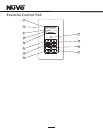
LEFT
RIGHT
LEFT
RIGHT
8
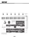
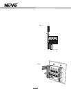
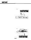
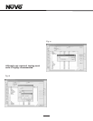
II. Terminating the Speaker Wire (Fig. 2)
All NuVo Systems operate across a homerun wiring scheme
using CAT5 for the zone’s Control Pad communication and
control, and a separate run of speaker wire for each zone.
The Essentia operates differently in that its zone speaker
wire termination is made at the Allport hub. The suggested
wire for this purpose is 16-gauge, 2- or 4- conductor
speaker wire rated for in-wall use.
The termination is performed using a modular Euro
connector. Each conductor is screwed down to the Euro
connector and plugged into the appropriate zone speaker
connection on the back of the Allport. The proper
termination for each zone is Left channel: and +, and Right
channel: and +.
I
jacks is irrelevant to the system’s operation. Six modular
Euro connectors are used to terminate the speakers in
each zone, see Section II, Terminating the Speaker Wire.
Once the speaker and CAT5 terminations are complete, the
Allport can be installed.
The order in which the CAT5 cables are plugged into the
Fig. 2
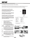
III. Installing the Essentia Amplifier
System setup works best when the amplifier is placed in the
same location as the audio source equipment. This is
typically in an audio rack, entertainment center, or a closet
dedicated to housing the home audio/video equipment. To
insure cool, reliable operation, we highly recommend
allowing one empty rack space above a Main or an Expander
amplifier unit. Also, insure there is ventilation around the
whole rack location.
The amplifier should be plugged in and the blue Standby LED
should be lit before proceeding with the remaining
installation. This activates protective circuitry for the
internal components.
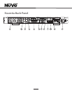
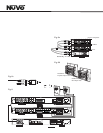
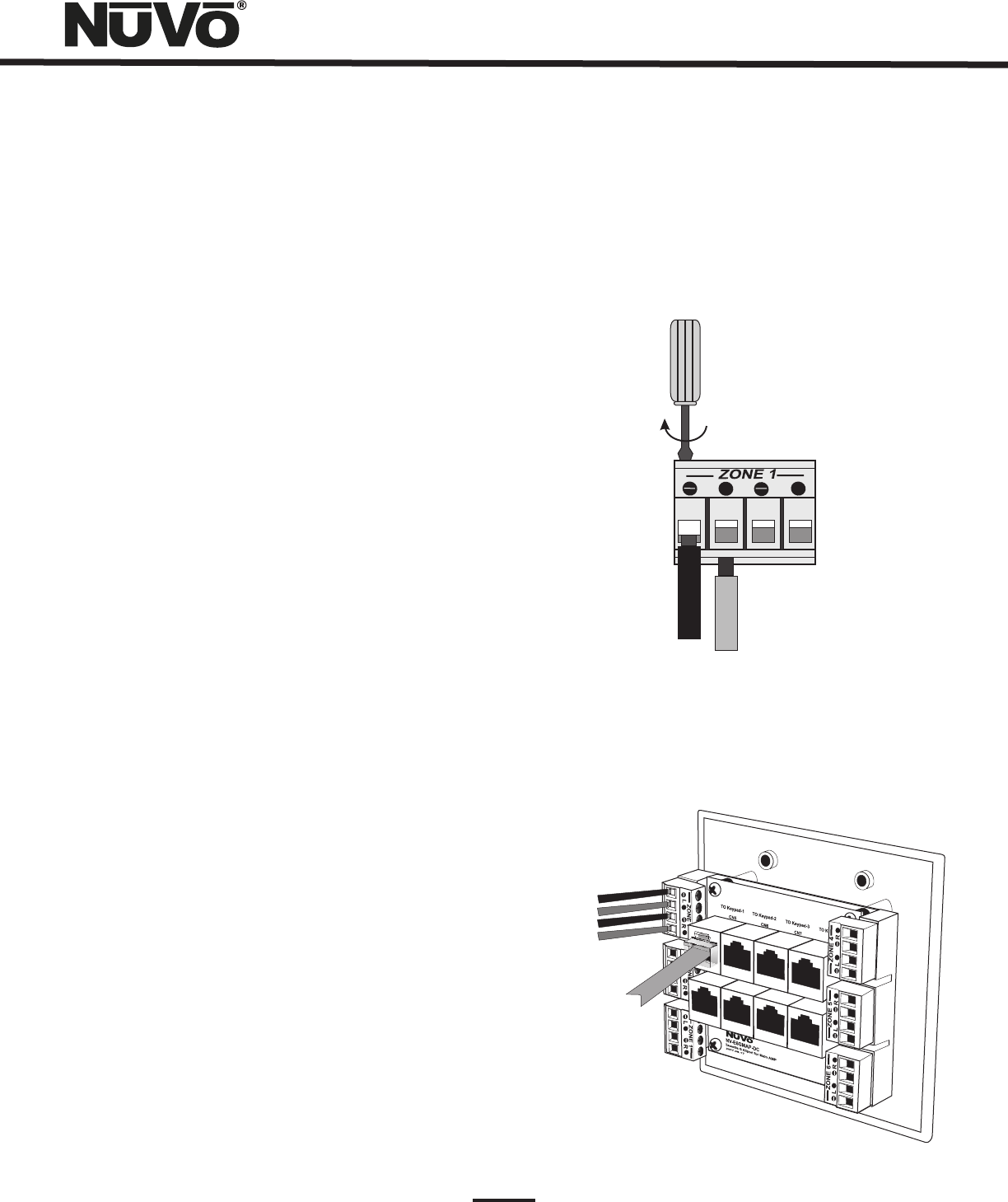
IV. Installing the NV-E6GMAP-DC Allport (Fig. 3)
The Allport is a multi-connection hub designed to accept all
the CAT5 and speaker wires from all zones of the Essentia
System. The location of the Allport should be determined by
the location of the Essentia amplifier. It is best to place it in
a wall behind the amplifier that can be easily accessible if
necessary.
The Allport is designed to fit into most any dual-gang
mounting ring, and has two sets of terminations on the
backside. Eight RJ45 jacks are meant for the Control Pads in
up to six zones, with one reserved for an additional Control
Pad and another for a link jack used for expansion from six
to twelve zones.
Fig. 3
+
+
+
+
+
+
+
+
+
+
+
+
+
+