NIStune Type 1 Hardware Installation Page 28 of 28
8. Installing In The Vehicle
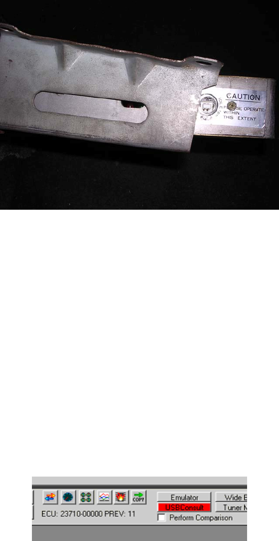
Put the ECU casing back together and reinstall ECU into the metal bracket. The diagnostic indicator now
containing the USB-B port should be accessible as seen below.
Reinstall ECU into vehicle. You may need to enlargen kick panel diagnostics hole for correct line up of the
USB-B connector to the ECU. Use a drill to enlargen the hole.
Connect the USB cable to the ECU through this port and other end to the laptop. Turn the vehicle Ignition
switch to ‘ON’ without starting the car
Your fuel pump should operate as normal and the car should be able to start. If not then immediately turn
off the engine and attempt to diagnose the problem following the NIStune diagnostics document.
If your ECU pulses the fuel pump, injectors, fuel regulator, flashes LEDs randomly (or they just stay on) or
does not start then your ECU could be reading a corrupt ROM image. Testing has shown that a corrupt ECU
can keep the heater element on longer than 1 second and blow it like a fuse. Ensure a corrupted image in
your ECU is rectified immediately and is powered off if corruption is suspected to avoid this situation
possibly occurring to you.
Following NIStune USB device installation, configuration and connection, pressing the ‘USB Consult’
button should highlight in red, and viewing the ‘Consult Display’ should show the battery, temperature and
AFM voltages.
Turn the vehicle Ignition switch to ‘START’ briefly to run the engine. Whilst the engine is running the
‘Consult Display’ should indicate more parameters and maptracing should be available in the various
graphic windows available from the NIStune software.
Refer to the NIStune Software Operators Manual and Type 1 QuickStart Manual for more information
regarding the installation of USB drivers and usage of the NIStune software.
Refer to the NIStune Diagnostics Manual if you have problems connecting to the NIStune board.


