


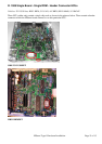

NIStune Type 1 Hardware Installation Page 13 of 13
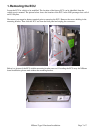
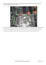
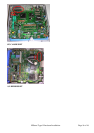
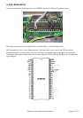
2. Where the 28 pin ROM has been removed, replace this with a 28 pin machine drilled socket. Fill in the
throughholes where the 24 pin ROM was mounted with solder. Note the orientation of the socket must have
the crescent indent facing the same direction of the previously installed ROM chip.
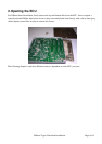
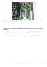
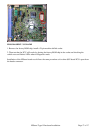
3. Use some holder to connect J4 to J3 as seen in the picture above. This will enable useage of only the 28
pin chip now.
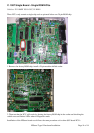
4. Verify ECU operation with new socket using only the factory 28 pin ROM chip. The LEDs should flash
when in diagnostic mode, and vehicle should function as normal. If not then immediately remove power and
recheck your soldering
Installation of the NIStune board now follows the same procedure as for other 6802 based ECUs.