


NIStune Type 1 Hardware Installation Page 10 of 10
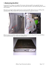
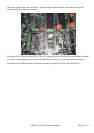
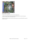
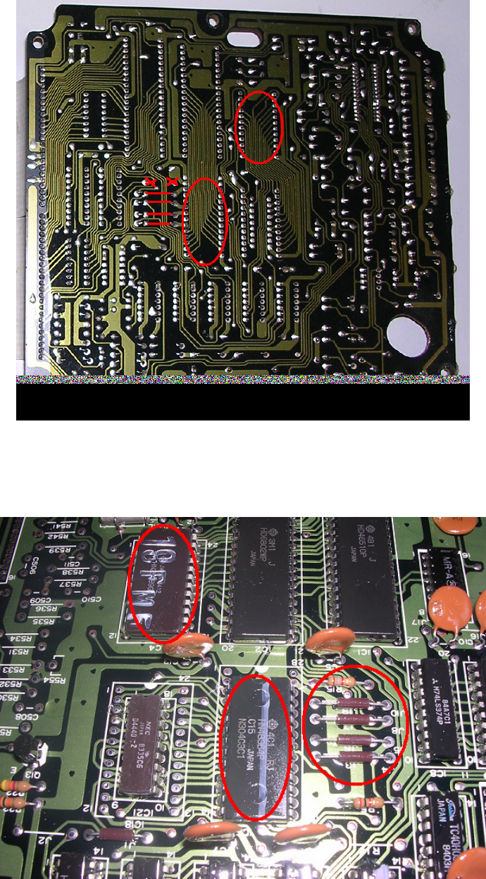
To remove the two ROM chips (U3 and U4) desolder from the top side of the ECU. Be very careful with
the heat of the desoldering gun because the pads on these ECUs lift very easily. It doesn't take much to
break a track on these earlier circuit boards.
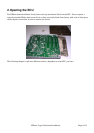
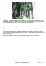
Insert the supplied IC socket in IC3 and solder in. Fill in the through holes if IC4 with solder.
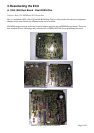
Next remove the four brown jumpers. These are J4, J5, J8 and J10. You can shorten these existing jumpers
positions to J3, J6, J7 and J9 by desoldering one end and repositioning it. Be careful when desoldering the
track to ensure that it does not lift. These ECUs are very old and the circuit boards are fragile.