NIStune Type 1 Hardware Installation Page 25 of 25
6. Inserting The Board
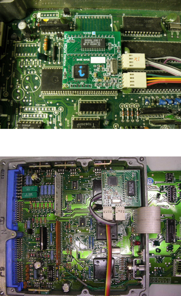
Push the NIStune board into the machine drilled socket previously installed. Connect the CPU cable to
connector X1 and the USB cable to connector X2.
Ensure the PGM jumper is not soldered if the board was previously programmed.
Where there is a knock sensor board, being wary of the knock sensor cable. If the JTAG programming pins
pointing upwards appear to touch components of the knock sensor board, these can be trimmed back with
wire cutters, as these are only used during factory programming.
R31/Z31/VLT Installation
S13 CA18/M30 VG30/A31 RB30/S13 KA24E Installation


