


NIStune Type 1 Hardware Installation Page 23 of 23
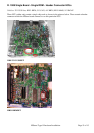
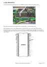
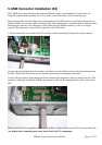
5. USB Connector Installation (X2)
The USB-B style connector that comes with the NIStune board is recommended for install where the
diagnostic potentiometer normally sits. It is up to the owner where they wish to locate this port.
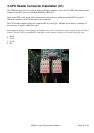
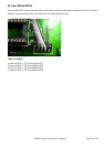
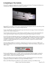
The existing bracket from the diagnostic potentiometer fits the USB connector, but requires the hole to be
drilled and filed out to fit the connector plug through. The potentiometer is normally used for idle fine select
and diagnostic indicator. The diagnostics can be retrieved from NIStune software, so this is no longer
required. The diagnostics selector will be replaced by the USB socket
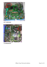
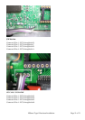
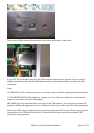
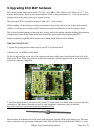
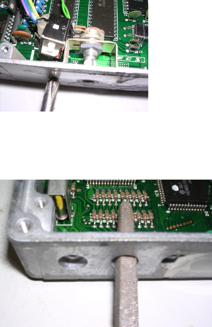
1. Firstly remove the screws under the ECU warning socket connecting the diagnostics selector bracket.
Unscrew the potentiometer from the bracket, and either cut or desolder the wires to the potentiometer from
the ECU. Ensure that if the wires are cut, that the exposed ends are adequately insulated.
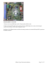
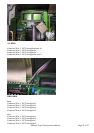
Using a drill size slightly larger than the hole that contained the diagnostics selector, enlarge this hole. This
must be of sufficient size that the USB-B type connector cable can fit through the hole to the socket in the
ECU.
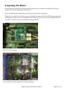
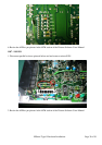
Ensure that all ECU housing debris caused by the drilling is blown away from the ECU circuitry afterwards.
Any debris that is remaining may cause short circuit to ECU components.