


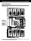
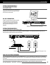
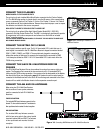
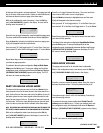
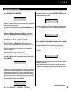
Figure 12. Connecting IR Flashers to ZR-4
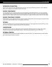
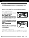
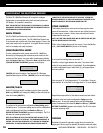
MultiZone Receiver
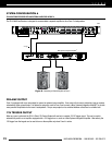
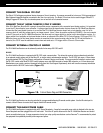
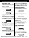
Figure 13. T568A wire termination
FLASHERS ZONE 1 AUDIO KEYPAD ZONES
2
4
L
R
3
HP
HT Sync
12 V
Trigger
RS 232
AM/FM
Fix Var
IR In
Global
1 2
3 4
Expansion
2
3 4
L
R
Page
ZONE 2 ZONE 3 ZONE 4
Pre Out
120 Volts ~ 60Hz. 1500 Watts Max.
8 Ω (4 Ω Min.)
Speaker Outputs
8 Ω (4 Ω Min.)
Speaker Outputs
8 Ω (4 Ω Min.)
Speaker Outputs
8 Ω (4 Ω Min.)
Speaker Outputs
L+ L- R- R+
L+ L- R- R+
L+ L- R- R+
L+ L- R- R+
L+ L- R- R+
L+ L- R- R+
L+ L- R- R+
L+ L- R- R+
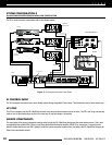
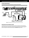
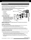
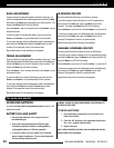
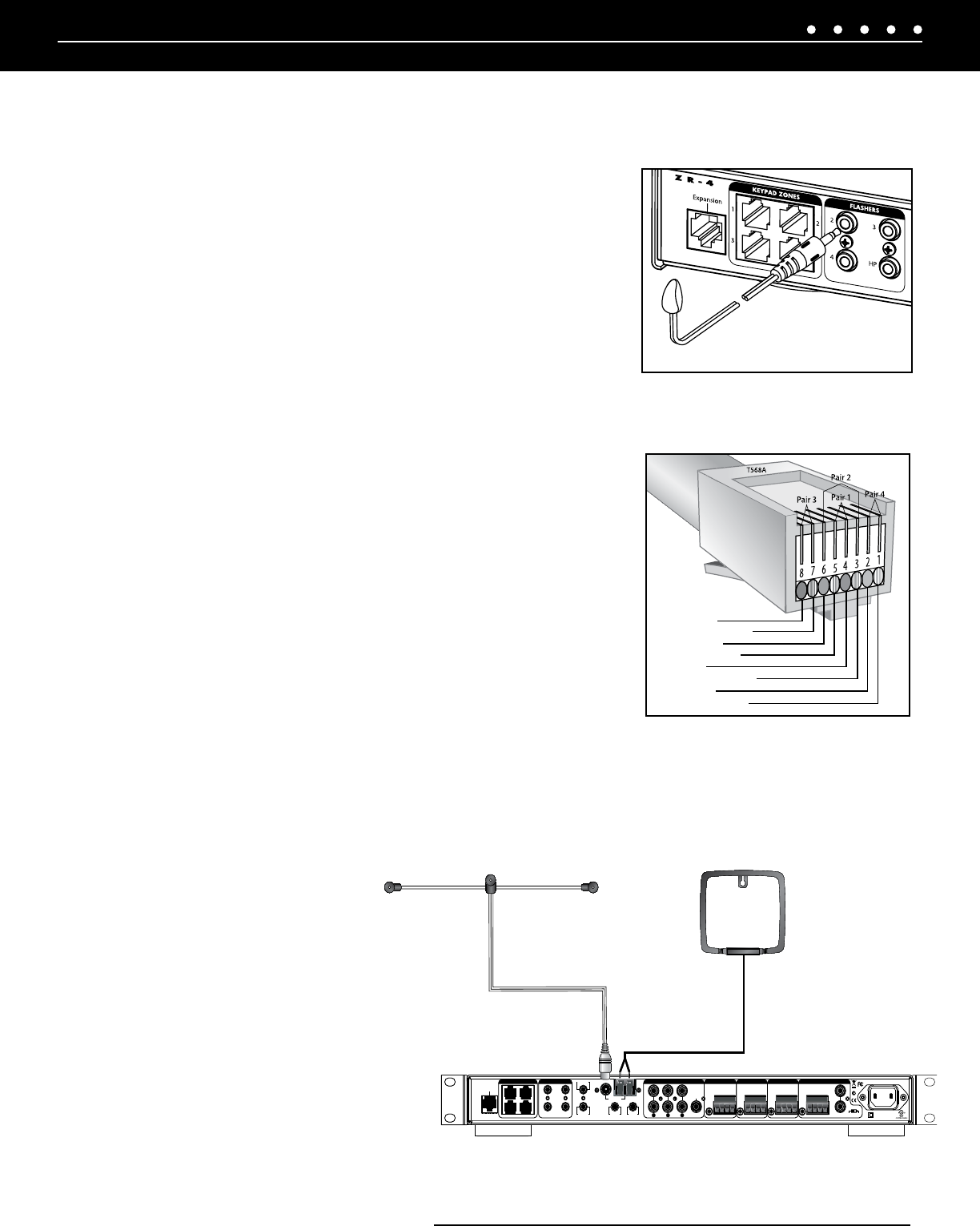
Figure 14. Connecting AM/FM Antennas to ZR-4 MultiZone Receiver
8= BROWN
7= BROWN/WHITE
6= ORANGE
5= BLUE/WHITE
4= BLUE
3= ORANGE/WHITE
2= GREEN
1= GREEN/WHITE
15NILES AUDIO CORPORATION – 1-800-BUY-HIFI – 305-238-4373
CONNECT THE IR FLASHERS
MICROFLASHER
®
TO THE FLASHER OUTPUTS
The mini-plug of each included Niles MicroFlasher connects into the Flasher Outputs
2-4. The MicroFlasher portion is placed directly over the IR sensor of the corresponding
source component (Source 2 for Flasher 2, Source 3 for Flasher 3, Source 4 for Flasher
4) and adheres with the included adhesive. Remove the protective paper cover to expose
the adhesive and attach to the source component.
HIGH-OUTPUT FLASHER TO THE HIGH OUTPUT FLASHER PORT
The mini-plug of an optional Niles High Output Flasher, Model IRB-1 (FG01023),
connects to the High Output Flasher Port. The IRB-1 is strategically positioned to provide
IR transmission to all source components and adheres to a shelf with an included
Velcro
®
mounting system.
CAUTION: DO NOT CONNECT MICROFLASHERS TO THIS PORT. THE HIGH OUTPUT FLASHER PORT
WILL DAMAGE MICROFLASHERS
CONNECT THE KEYPAD CAT-5 CABLES
Each Keypad controls a specific zone. The RJ-45 terminated CAT-5 cable that runs to
each keypad is connected to the ZR-4 MultiZone Receiver’s keypad connectors labeled:
ZONE 1, ZONE 2, ZONE 3, and ZONE 4. The zone that each keypad is connected to
defines the number of that zone. For example: the keypad that is connected to ZONE
1 will always be defined as ZONE 1. All RJ-45 terminated CAT-5 cable must utilize the
T568A wiring convention.
CONNECT THE SLAVE ZR-4 MULTIZONE RECEIVER
CHASSIS
Two ZR-4 MultiZone Receiver Kits can be combined to create a four-source, eight-zone
system. The Expansion Port connects the two receivers by a RJ-45 terminated CAT-5
cable using the T568A wiring convention. One receiver must be designated as the Master,
the other as the Slave (see configuration page 8). All flashers for source control must be
connected to the Master and not to the Slave. IR from the keypads connected to the Slave
chassis will be routed to the Master chassis via the expansion connection port.
CONNECT THE AM AND FM ANTENNAS
When using two ZR-4 MultiZone Receiver
kits to create an 8-zone system, antennas
must be connected to both ZR-4 MultiZone
Receivers.
FM DIPOLE ANTENNA
The included FM Dipole Antenna connects to the
female 75 ohm coaxial connector. The antenna is
then positioned and mounted for best reception.
AM LOOP ANTENNA
The included AM Loop Antenna connects
with its bare-wire ends to the spring-loaded
terminals labeled AM and GND. The antenna
is then positioned and mounted for best
reception.