


NOTES ON INSTALLATION
Your NAD T770 should be placed on a firm, level surface. Avoid
placing the unit in direct sunlight or near sources of heat and damp.
Allow adequate ventilation. Do not place the unit on a soft surface
like a carpet. Do not place it in an enclosed position such a bookcase
or cabinet that may impede the air-flow through the ventilation slots.
Make sure the unit is switched off before making any connections.
The RCA sockets on your NAD T770 are colour coded for
convenience. Red and white are Right and Left audio respectively,
orange for digital input, black for RF modulated digital signal,
yellow for Video Composite and NAD Link.
Use high quality leads and sockets for optimum performance and
reliability. Audio RCA leads will function correctly for video
signals, although it is recommended to use dedicated video leads
where possible. For the digital inputs use dedicated leads for
digital signal transfer. Ensure that leads and connectors are not
damaged in any way and all connectors are firmly pushed home.
For best performance, use quality speaker leads of 16 gauge
(1.5mm) thickness or more. If the unit is not going to be used for
some time, disconnect the plug from the AC socket.
Should water get into your NAD T770, shut off the power to the
unit and remove the plug from the AC socket. Have the unit
inspected by a qualified service technician before attempting to
use it again. Do not remove the cover, there are no user-
serviceable parts inside.
Use a dry soft cloth to clean the unit. If necessary, lightly dampen
the cloth with soapy water. Do not use solutions containing benzol
or other volatile agents.
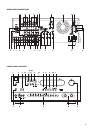
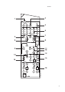
REAR PANEL CONNECTIONS
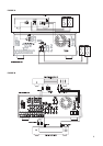
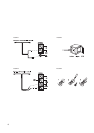
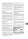
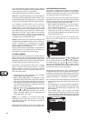
1. AM ANTENNA
An AM loop antenna is supplied with the T770 and is required for AM
reception. Open the clip terminal lever and insert the wire from the
antenna. Closing the lever will lock the wire in place (Fig. 3). Test
various positions for the antenna, but always ensure the loop is placed
vertically for best reception. Placing the antenna close to large metal
items such as metal shelves or radiators may interfere with reception.
NOTE: When reception is not satisfactory using the supplied AM
loop antenna alone, connection of an external antenna is
recommended. Do not connect anything other than a loop antenna
to the AM ANTENNA terminal. Do not remove the AM loop antenna.
The antenna cable to the loop antenna must not exceed 3 meters.
2. FM ANTENNA
A ribbon wire FM antenna is included and should be connected to
the FM connector at the rear of the unit (Fig. 1, Fig. 2). The ribbon
aerial should be mounted on a vertical surface and placed so that
it forms a ‘T’.
Experiment with placement of the antenna to find the position that
gives the best signal strength and lowest background noise. An
inadequate FM signal normally results in high levels of hiss,
especially in stereo, and interference from external electrical
sources. In areas of poor FM reception, the tuner section’s
performance can be improved by using an externally mounted FM
antenna. A qualified aerial installer will be able to advise and fit a
recommended aerial for your reception conditions.
3. AUX INPUT
Input for audio components. Use a twin RCA-to-RCA lead to connect
the audio component left and right ‘Audio Outputs’ to this input.
4. CD INPUT
Input for CD player (analogue audio signal) or other line-level
signal source. Use a twin RCA-to-RCA lead to connect the CD
player’s left and right ‘Audio Outputs’ to this input.
5. TAPE 1
Connections for analogue recording and playback to an audio
tape recorder of any type, such as a cassette, reel-reel, DAT, MD
or DCC. Using twin RCA-to-RCA leads, connect to the left and right
‘Audio Output’ of the tape machine to the TAPE 1 IN connectors
for playback. Connect the left and right ‘Audio Input’ of the tape
machine to the TAPE 1 OUT connectors for recording.
6. TAPE 2
Connections for analogue recording and playback to a second
audio tape recorder of any type. Using twin RCA-to-RCA leads,
connect to the left and right ‘Audio Output’ of the tape machine to
the TAPE 2 IN connectors for playback. Connect the left and right
‘Audio Input’ of the tape machine to the TAPE 2 OUT connectors
for recording.
7. VIDEO 1 & VIDEO 2 (AUDIO)
Connections for the audio recording and playback to a VCR or
other video recorder. Using twin RCA-to-RCA leads, connect to the
left and right ‘Audio Out’ of the VCR to the VIDEO 1 or VIDEO 2 IN
connectors for playback. Connect the left and right ‘Audio In’ of
the VCR to the VIDEO 1 or VIDEO 2 OUT connectors for
recording. These audio inputs and outputs are used in
conjunction with the composite (line) video (refer to No. 9
below) or S-VIDEO (refer to No. 12 below) inputs and outputs.
8. VIDEO 3 & VIDEO 4 (AUDIO)
Inputs for the audio playback from a VCR or other video device
such as a stereo TV, satellite or cable TV receiver or a Laser Disc.
Using twin RCA-to-RCA leads, connect to the left and right ‘Audio
Out’ of the VCR/TV/LD/satellite receiver to these inputs. These
audio inputs are used in conjunction with the composite (line)
video (refer to No. 10 below) or S-VIDEO (refer to No. 12 below)
inputs.
9. VIDEO 1 & VIDEO 2 (VIDEO)
Connection for the Composite video signal input for VIDEO 1 or
VIDEO 2. Using a RCA-to-RCA lead, connect the ‘Video Out’ of the
VCR to VIDEO 1 or VIDEO 2 IN for playback. Connect VIDEO 1 or
VIDEO 2 OUT to the ‘Video In’ of the VCR to copy video signals
from VIDEO 1 to VIDEO 5.
10. VIDEO 3 & VIDEO 4 (VIDEO)
Connection for the Composite video signal input for VIDEO 3 or
VIDO 4. Using an RCA-to-RCA lead, connect the ‘Video Out’ of the
VCR, TV, Laser Disc or satellite/cable unit. VIDEO 3 & VIDEO 4 can
be used for video playback only. Use VIDEO 1 or VIDEO 2 if you want
to connect a VCR for recording and playback through the T770.
11. MONITOR OUT
Composite video output for connecting a TV or Video Monitor to
view video sources connected to VIDEO 1 to VIDEO 5. Using a
Video RCA-to-RCA lead, connect the ‘Video Line In’ on the TV or
monitor to the MONITOR OUT.
GB
8
NAD T770 Surround Sound Receiver