


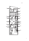


REMOTE CONTROL
STAND-BY button (green, No. 1 on remote control drawing):
Press this button to switch the unit from operating to the Stand-by
mode and vice versa: Press this button again to switch the unit on from
Stand-by; the last selected source will be indicated in the display.
NOTE: Stand-by mode is indicated by the Stand-by indicator
(No. 2) just over the green POWER button on the front panel
(No. 1). In Stand-by mode the T770 uses very little power.
However, it is recommended that you switch the unit totally off if
it is not going to be used for more than a couple of days. Switch
off completely by pressing the POWER button on the front panel
(No. 1), all lights will extinguish. Press this button to switch the
unit on. To switch the unit off, press this button again.
2. STANDBY
This green LED will light up when the receiver is switched On, but
in Stand-by mode. Refer to section 1 in this chapter for more
information. The LED will also light up when the receiver receives
a remote control command from the supplied handset.
3. SPEAKERS A, B
Pressing the Speakers A button will disengage the main
loudspeaker system (the Front A, Center and Surround speakers).
Press the button again to switch the speakers back on.
Pressing the Speakers B button will disengage the secondary
speaker system (the Front B speakers). When Speakers B is
selected any surround mode will be switched off automatically;
Surround off (stereo) will be selected.
Speakers A and Speakers B can not be used simultaneously. When
selecting Speakers B, Speakers A will be disengaged and vice versa.
The display panel indicates which speakers system has been selected.
NOTE: Always turn the volume down when engaging or
disengaging either Speaker A or Speaker B.
4. HEADPHONE SOCKET
A 1/4” stereo jack socket is supplied for headphone listening. The
socket has its own amplifier, which will drive conventional
headphones of any impedance. The volume and tone controls are
operative for headphone listening. Use a suitable adapter to connect
headphones with other types of connectors such as 3.5mm stereo
‘personal stereo’ jack plugs. Inserting a headphone will automatically
disengage the subwoofer output and turn off all speakers connected.
The sound from the AC-3 RF input is not passed on to the
headphones socket. Also connect the analogue output from the
AC-3 RF source connected to Digital Audio Input 3 to be able to
listen to Video 4 via headphones. The sound from the EXT. 5.1 CH
input is not available on the headphones socket.
NOTE: Listening at high levels can damage your hearing.
5. VIDEO 5 INPUT
For easy and temporary connection you can connect a camcorder
(playback only) or video game console. If the game console or
camcorder is mono, connect the audio lead to the R (Right) audio
socket.
If your camcorder is equipped with S-Video (so-called “Hi-8” and
“S-VHS” models) cameras you can use the S-Video input. Refer
also to chapter “Rear Panel connections”, section 12 for
additional information.
The Video 5 input works in the same was as Video 3 and Video 4,
refer to chapter “Rear Panel connections”, section 10 for
additional information.
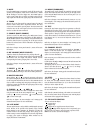
6. INPUT AND MONITOR SELECTORS
These buttons select the active input to the T770 and the signal sent
to the loudspeakers, Tape 1 & 2, Video 1 & 2 and TV monitor outputs.
The name of the Input and Surround Mode will be shown in the
Display Panel.
VIDEO 1 & VIDEO 2 Selects the VCR connected to VIDEO 1 or
VIDEO 2 as the active input. “VIDEO-1” or “VIDEO-2” is shown in the
Display Panel when selected.
VIDEO 3 & VIDEO 4 Selects the signal from stereo
TV/Satellite/Cable receiver or Laser Disc connected to VIDEO 3 or
VIDEO 4 as the active input. "VIDEO-3" or "VIDEO-4" is shown in the
Display Panel when selected.VIDEO 5 Selects the camcorder or video
game console connected to the Video 5 front panel inputs as the
active input. “VIDEO-5” is shown in the Display Panel when selected.
VIDEO 5 Selects the camcorder or video game console connected to
the Video 5 front panel inputs as the active input. “VIDEO-5” is shown
in the Display Panel when selected.
TAPE 1 Selects Tape 1 as the active input.
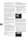
TAPE 2 MONITOR Selects the output from a tape recorder when
playing back tapes or monitoring recordings being made through the
Tape 2 sockets. Press the Tape 2 button once to select it and again to
return to the normal input selection.
Tape 2 is a Tape Monitor function, which does not override the
current input selection. For example, if the CD is the active input
when TAPE 2 is selected, then the CD signal will continue to be
selected and sent to the TAPE 1, TAPE 2, Video 1 and Video 2 OUT
sockets, but it is the sound from recorder connected to Tape 2 that
will be heard on the loudspeakers. When Tape 2 Monitor is selected,
“TAPE 2” is indicated in the alphanumeric section of the display for
3 seconds before it defaults to indicating the active input again. The
box just over the alphanumeric section indicating “T-2 MONITOR”
will remain lit until Tape 2 is disengaged again.
FM Selects FM radio. FM is also automatically selected when an FM
Preset is selected.
AM Selects AM radio. AM is also automatically selected when an AM
Preset is selected.
AUX Selects the auxiliary audio component as the active input.
CD Selects the CD as the active input.
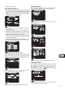
VIDEO OUTPUT The video signal available on the S-Video and Video
Composite Monitor, Video 1 and Video 2 outputs is dependent on the
selected video input (VIDEO-1, VIDEO-2, VIDEO-3, VIDEO-4, VIDEO-
5). However, when one of the audio-only sources is selected (TAPE-
1, TAPE-2, FM, AM, AUX, CD) the last selected video signal from one
of the video inputs will be present on these outputs. This way you can
watch a Laser Disc or video whilst listening to the CD player.
The display indicates which video signal is routed to the MONITOR,
Video 1 and Video 2 outputs in the far left of the display area.
NOTE: To avoid “feedback” the video input signal from Video 1
or Video 2 is not available on their own outputs (e.g. When Video
2 is selected, the video signal will be available on the Monitor and
Video 1 outputs, but not on the Video 2 outputs).
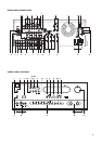
VOLUME AND TONE FUNCTIONS
7. TONE DEFEAT
The Tone Defeat switch by-passes the tone control section of the
T770. If the Tone Controls (No. 8) are not normally used and left
in the 12 o’clock position, then it is advisable to switch out the
Tone Control section altogether by using this switch. In the ‘out’
position, the Tone Control circuits are active, pushing the Tone
Defeat switch in bypasses the Tone Control section.
GB
11