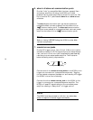
18
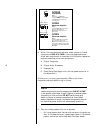
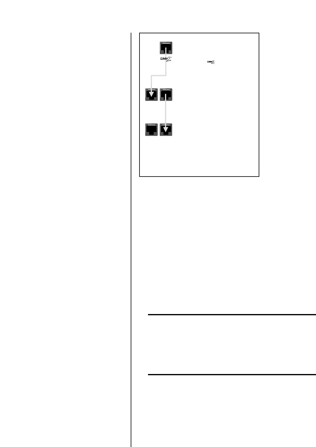
slave out
Nº320S
Preamplifier
Step A:
Connect the (slave out)
communication port on the preamplifier
to the slave in communication port
on the first Nº33H
Nº33H
Monaural Amplifier
Step B:
Connect the slave out communication
port on the first Nº33H to the
slave in communication port on the
second Nº33H.
Nº33H
Monaural Amplifier
Step C:
Connect the slave out communication
port on the second Nº33H to the
slave in communication port on a third
power amplifier. This step can be repeated
to include up to six power amplifiers in the
slave chain.
slave in
slave inslave out
3. When Link connections have been made, power on linked
components ONE AT A TIME in the order specified below.
Allow each component to complete its initialization sequence
before proceeding to the next component.
A. Digital Transports
B. Digital Audio Processors
C. Preamplifier
D. Power Amplifiers (begin with the first power amplifier in
the slave chain)
At this point, the front panel standby LEDs on all linked
components should be blinking in unison.
Note
Linked components must be powered on ONE AT A TIME
in the specific order listed in step 3 (above) to ensure proper
functioning of Link controls. DO NOT use a power strip
switch to power on several components at once. When
power is supplied to a strip, connected components that do
not include a power button will automatically power on.
4. Take the linked preamplifier out of standby.
• All linked power amplifiers should come out of standby as
well. If this does not occur, repeat steps 3 and 4. If problems
persist, contact an authorized Mark Levinson dealer.


