


5
ENGLISH
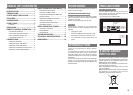
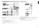
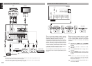
, AC IN
Connect to supplied an AC power cord, and connect
to an AC power outlet.
SR4021 has to be powered by 230V AC only.
. Speaker terminals
Connect your speaker system(s) to these terminals.
There are two sets of terminals, so you can connect
either 1 and/or 2 speaker systems.
⁄0 MAIN IN jacks
Use these jacks to connect an extension pre amplifi er
or graphic equalizer.
When a graphic equalizer is to be connected,
connect its output jacks with the MAIN IN jacks on
this unit.
When not used, leave these jacks connected with the
supplied connecting pins.
⁄1 PRE OUT jacks
Use these jacks to connect an extension power
amplifi er or graphic equalizer.
When a graphic equalizer is to be connected,
connect its input jacks with the PRE OUT jacks on
this unit.
When not used, leave these jacks connected with the
supplied connecting pins.
⁄2 AUDIO IN/OUT
(PHONO, CD, RECORDER 1,
RECORDER 2)
These are the analog audio inputs and outputs. There
are 8 audio inputs (4 of which are linked to video
inputs) and 3 audio outputs (1 of which is linked to
video output). The audio jacks are nominally labeled
for recorder1 (CD recorder) recorder2 (cassette tape
deck), compact disc players, DVD players and etc....
The audio inputs and outputs require RCA-type
connectors.
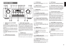
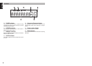
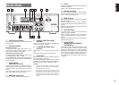
REAR PANEL
b REMOTE CONTROL IN/OUT
terminals
Connect to a Marantz component equipped with
remote control (RC-5) terminals.
n FLASHER IN (Flasher input
terminal)
This terminal is to control the unit from another
zone.
Connect the control signal from a Keypad, etc.
m AC OUTLET
Connect the AC power cord of component such as a
DVD or CD player to this outlet.
The marked SWITCHED provides power only when
the SR4021 is turned on and is useful for components
which you use every time you play your system.
Caution:
• In order to avoid potential turn-off thumps, anything
plugged into these outlets should be powered up
before the SR4021 is turned on.
• The capacity of this AC outlet is 150W. Do not
connect devices that consume electricity more than
the capacity of this AC outlet. If the total power
consumption of the connected devices exceeds the
capacity, the protection circuit shuts down the power
supply.
z GND (ground) terminal
Connect the grounding wire from the analog turntable
to this terminal.
x Antenna terminals
FM antenna terminal
For connecting the supplied FM antenna or for
connecting an external FM antenna with a coaxial
cable, or for connecting a cable network.
AM antenna and ground terminal
For connecting the supplied AM loop antenna. Use
the terminals marked “AM” and “GND”.
The supplied AM loop antenna will provide good AM
reception in most areas. Position the loop antenna to
the best reception.
c VIDEO IN/OUT
(AUX, DSS, DVD, VCR)
These are the video inputs and output. There are 4
video inputs and 1 video output. Connect VCR, DVD
players, and other video components to the video
inputs.
The 1 video output can be used to be connected to
video tape recorder for making recording.
v MONITOR output jack
Connect to the TV’s video input (VIDEO IN) jack.
230V 50/60Hz
230V 50/60Hz
IN
IN
SYSTEM 2
SYSTEM 2
150W 1A MAX.
150W 1A MAX.
AC OUTLET
AC OUTLET
SWITCHED
SWITCHED
IN
IN
AM
AM
FM
FM
(
(
75
75
)
)
PHONO
PHONO
IN
IN
IN
IN
OUT
OUT
IN
IN
OUT
OUT
DSS
DSS
GND
GND
AUX
AUX
VIDEO
VIDEO
SYSTEM 1
SYSTEM 1
CONTROL
CONTROL
REMOTE
REMOTE
GND
GND
VCR
VCR
IN
IN
OUT
OUT
L
L
ANTENNA
ANTENNA
IN
IN
OUT
OUT
IN
IN
OUT
OUT
OUT
OUT
IN
IN
IN
IN
IN
IN
IN
IN
OUT
OUT
IN
IN
IN
IN
(CD-R)
(CD-R)
(TAPE)
(TAPE)
AUX
AUX
CD
CD
DSS
DSS
PRE
PRE
DVD
DVD
RECORDER 2
RECORDER 2
MAIN
MAIN
VCR
VCR
RECORDER 1
RECORDER 1
IN
IN
R
R
DVD
DVD
AUDIO
AUDIO
R
R
MONITOR
MONITOR
FLASHER
FLASHER
AC IN
AC IN
L
L
R
R
L
L
MODEL NO. SR4021
MODEL NO. SR4021
SYSTEM
SYSTEM
1
1
:
:
4 - 16 OHMS
4 - 16 OHMS
SYSTEM
SYSTEM
2
2
:
:
4 - 16 OHMS
4 - 16 OHMS
SYSTEM
SYSTEM
1+2
1+2
:
:
8 - 16 OHMS
8 - 16 OHMS
3 4 5 6 7
1112
1 8
10
22
9