


8
ENGLISH
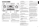
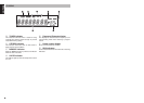
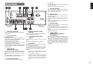
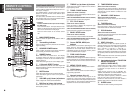
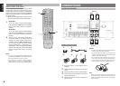
FUNCTION AND OPERATION
AMP
1, 2, 3
INFO
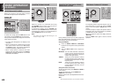
REMOTE CONTROL CODE SETTING
The remote control unit contains 3 sets of remote
control codes, and it can be used to control up to 3
receivers in one location. To control a second or third
receiver, select the remote control code as explained
below. The selected receiver can be operated from
the remote control.
• When the unit is shipped from the factory, the main
unit and remote control are set to RECEIVER1.
1.
RECEIVER2
To set the remote control to RECEIVER2,
hold down both the AMP button and 2 number
button on the remote control for at least fi ve
seconds.
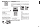
RECEIVER3
To set the remote control to RECEIVER3,
hold down both the AMP button and 3 number
button on the remote control for at least fi ve
seconds.
2.
Also set the main unit’s remote control setting
to the same setting as the remote control.
To
change main unit’s remote control setting,
hold down both the AMP and INFO buttons
on the remote control; the remote control
setting (“RECEIVER 1”, “RECEIVER 2” or
“RECEIVER 3”) will be displayed in the display
window on the main unit and main unit setting
will be changed same setting as remote
control.
Notes:
• To set the remote control back to RECEIVER1, hold
down both the AMP button and 1 number button on
the remote control for at least fi ve seconds.
•
If the batteries in the remote control are replaced
while the remote control is set to RECEIVER2 or
RECEIVER3, the setting will revert to RECEIVER1.
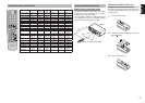
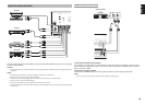
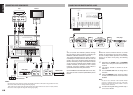
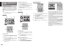
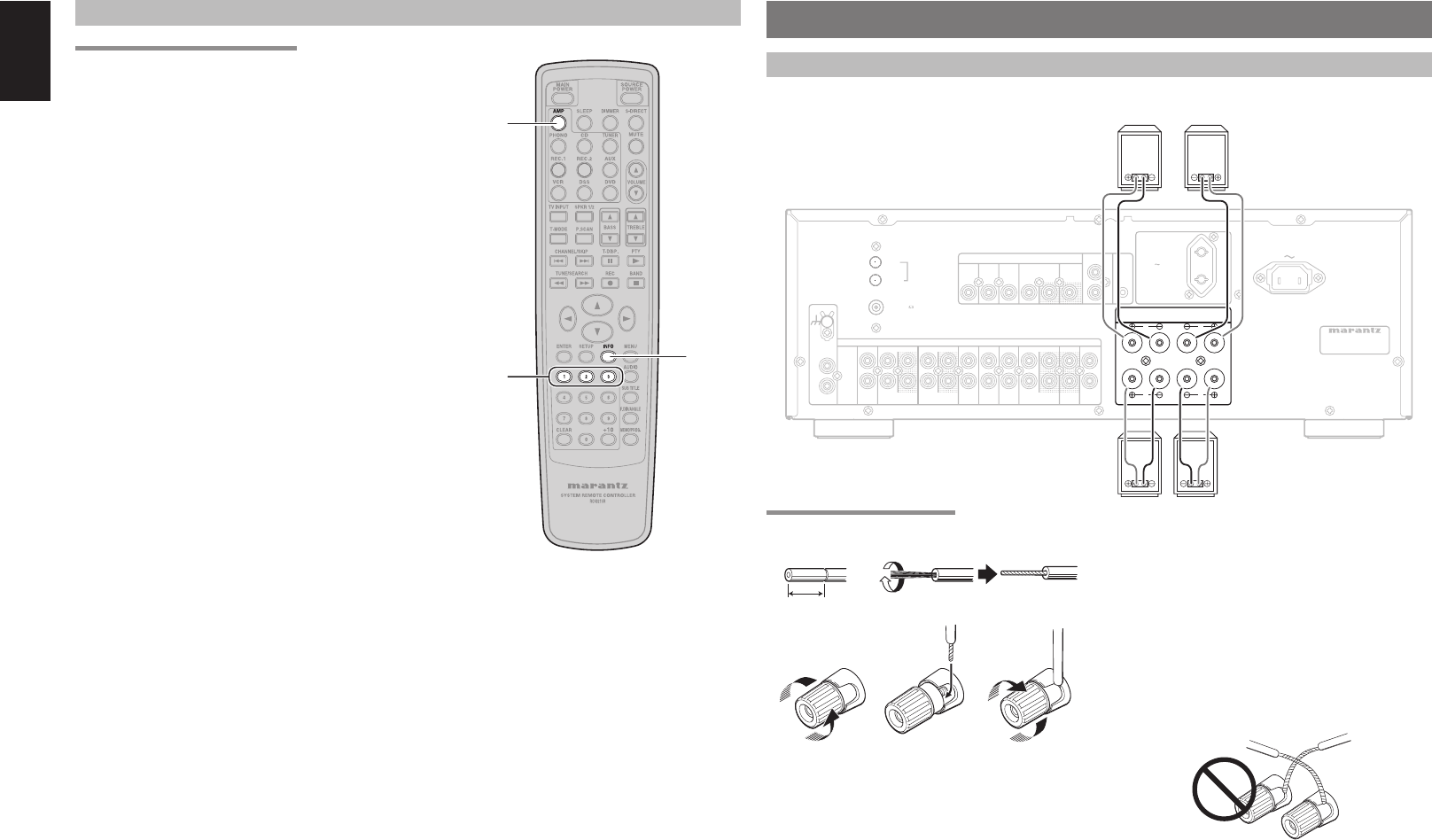
CONNECTIONS
CONNECTING SPEAKERS
System 2
Right Left
230V 50/60Hz
IN
SYSTEM 2
150W 1A MAX.
AC OUTLET
SWITCHED
IN
AM
FM
(
75
)
PHONO
ININ OUTIN OUT
DSS
GND
AUX
VIDEO
SYSTEM 1
CONTROL
REMOTE
GND
VCR
IN
OUT
L
ANTENNA
IN
OUT
INOUT OUT ININ IN
IN
OUTIN IN
(CD-R) (TAPE)
AUXCD DSS PREDVDRECORDER 2 MAINVCRRECORDER 1
IN
R
DVD
AUDIO
R
MONITOR
FLASHER
AC IN
L
R L
MODEL NO. SR4021
SYSTEM 2
SYSTEM 1
R
L
R L
SYSTEM 1 : 4 - 16 OHMS
SYSTEM 2 : 4 - 16 OHMS
SYSTEM 1+2 : 8 - 16 OHMS
System 1
Right Left
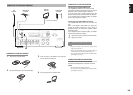
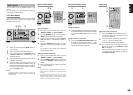
CONNECTING SPEAKER WIRE
1. 2.
3. 4. 5.
10 mm
(3/8inch)
1.
Strip away approx. 10 mm (3/8inch) of wire
insulation.
2.
Twist the bared wire ends tight, to prevent short
circuits.
3.
Loosen the knob by turning it counterclockwise.
4.
Insert the bare part of the wire into the hole in
side of each terminal.
5.
Tighten the knob by turning it clockwise to
secure the wire.
Caution:
• Be sure to use speakers with the specifi ed impedance
as shown on the rear panel of this unit.
• To prevent damage to circuitry, do not let the bare
speaker wires touch each other and do not let them
touch any metal part of this unit.
• Do not touch the speaker terminals when the power
is on. It may cause you to receive an electric shocks.
• Do not connect more than one speaker cable to one
speaker terminal. Doing so may damage this unit.
Note:
Be sure to connect the positive and negative cables for
the speaker properly. If they are miss-connected, the
signal phase will be reversed and the signal quality
will be corrupted.