


English
English
Français
Français
7
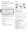
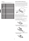
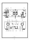
!1 Power Cord
Connect the power cord to a standard household power
outlet.
!2 Power Switch
Press this switch to turn power on (depressed) and off
(raised). Note that the power of any equipment connected
to the switched AC outlet on the rear panel (see 10 above) is
also turned on and off by operating this switch.
Turning on the power causes the POWER indicator to light,
and the POWER indicator goes out when power is turned
off.
While the POWER switch is in the ON position (depressed),
You can put use the remote control unit’s SYSTEM POWER
ON and OFF button to switch the amplifier between standby
(indicated when the @4 STANDBY indicator is lit) and power on.
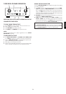
!3
Tape,CD-R/MD Selector Buttons
Press one of the these switches to select a connected tape
deck or CD-R(MD) for monitoring or playback. Pressing a
tape,CD-R/MD selector switch causes the indicator above it
to ligth.
Pressing TAPE,CD-R/MD SELECTOR button while the
amplifier is in the Standby Mode automatically tums power
back on.
!4 Input Selector
Use this selector to specify PHONO,CD, TUNER, AUX 1, or
AUX 2 as the program source for recording or play. Selecting
a program source causes the indicator above it to light.
Changing the INPUT SELECTOR setting while the amplifier
is in the Standby Mode automatically turns power back on.
!5 Remote Sensor
The remote sensor receive infrared commands from the
remote control unit. Note that the remote control unit must
be pointed directly at the remote sensor for proper operation.
!6 Volume Control
Rotate this knob clockwise to increase volume, and counter-
clockwise to decrease volume.
!7 Muting Indicator
This indicator lights when muting is activated by pressing
the remote control unit’s MUTING button.
IMPORTANT:
Be sure to double check the VOLUME control setting before
pressing the remote control unit’s MUTING button to cancel
muting. Restoring audio output while the VOLUME control
setting is too high can damage your speakers.
!8 Balance Control
Rotate this knob to shift the balance of stereo output left and
right. Note that turning the BALANCE control all the way in
either direction causes output from the other side to be
eliminated entirely.
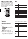
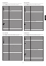
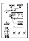
CONTROLS, CONNECTORS, AND INDICA-
TORS
(Figure 2)
q Remote Control Bus Terminals (REMOTE CONT.
BUS)
These terminals can used to connect other audio equipment
that is equipped with a remote control bus terminal.
Connection requires a special cable. The bus OUT terminal
sends signal to the connected equipment, while the bus IN
terminals receive signals.
w AUX1/AUX2 Input Jacks
These auxiliary input jacks can be used to connect the audio
output of a TV multiplex/stereo audio tuner, VCR, laserdisc
system, or other AV component audio output.
e Tuner Input Jacks
Connect these jacks to the output jacks of your tuner.
r CD Input Jacks
Connect these jacks to the output jacks of your compact
disc player.
t Phono Input Jacks
Connect these jacks to the output jacks of your turntable.
These input jacks are exclusive for a turntable equipped with
MM (Moving Magnet) cartridge.
y Tape / CD-R / MD In/Out Jacks
Connect these jacks to the play (output) and record (input)
jacks of your recorders. Up to two decks can be connected.
u Processor In/Out Jacks
Use these jacks to connect a graphic equalizer or other
analog audio processor. When not used, leave these jacks
connected with the supplied connecting pins.
i Ground Terminal
If your turntable has a grounding wire, connect it to this
terminal.
o Speaker Systems
Connect your speaker system(s) to these terminals. There
are two sets of terminals, so you can connect either one or
two speaker systems.
!0 AC Outlets (Switched)
Connect the power cord of another piece of equipment (VCR,
tuner, CD) when you want the power of the connected
equipment automatically turned on whenever you turn on this
amplifier. For this to work correctly, the power switch of the
connected equipment must be left on. Normally, the audio
output of the connected equipment is also connected to this
amplifier. Note that the total power consumption of the
connected all equipment must not exceed 120W.