


7
BEFORE USENAME OF PARTS
BASIC
OPERATION
ADVANCED
OPERATION
REMOTE CONTROLLER
OPERATION
TROUBLESHOOTING
OTHERS SETUP
SETUP
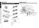
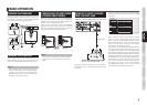
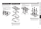
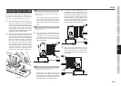
PREPARING THE LN-11S1A
Assemble the anamorphic lens and lens slider using
the supplied screws and washers.
Secure the projector to the base plate using the
specified screws, and secure the lens slider with
anamorphic lens attached to the base plate.
1. Secure the lens slider to the base plate
using the supplied machine screws (M3 x
8) in 6 locations.
When attaching to a VP series projector,
slide the lens slider to the end as shown in
Figure 7 and secure in place.
Figure 7
Slide this way.
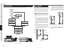
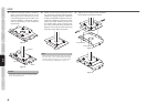
ASSEMBLING THE MOUNT20
Assemble the MOUNT20 by performing the steps
below, refer to Figure 8:
Plate #1
Plate #2
Platea #3
Plate #4
MOUNT20 and LN-11S1A Mounting plates
Figure 8
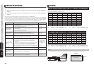
Note:
The MOUNT20 hardware, fasteners, mounting
template and parts list are located in a separate
shipping carton from the projector. Plate #4 will
be used when installing the MOUNT20 with the
projector.
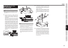
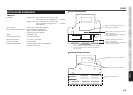
1. Insert Base Plate connectors q into
the lateral positioning slots e from the
underside of Plate 1.
The lateral positioning slots will give
you 2-1/4 inches of lateral adjustment for
projector alignment. Refer to Figure 9.
Plate #1
Base Plate Connectors q Projector Mount Ceiling Plate #1
Figure 9
q
q
w
w
w
e
e
r
r
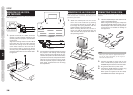
2. Base plate connector holes e provide 15
degrees of horizontal rotation adjustment.
Attach horizontal adjustment Plate #2 to
the projector mount ceiling Plate #1 using
the four (4) 5/16-18 inch nuts and washers
provided. Refer to Figures 10 and Figure 11
on page 8.
Figure 10
e
e
e
e
Plate #2
Plate #1
Note:
When the EXT10 Extension Pole will be used,
attach the “Outside Pole” end to Plate #1 (instead
of Plate #2) using four (4) 5/16-18 inch nuts and
washers provided. Refer to Figure 12 on page 8.
Wire
Access