


4
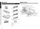
BEFORE USE NAME OF PARTS
BASIC
OPERATION
ADVANCED
OPERATION
SETUP
TROUBLESHOOTING
OTHERS
BASIC
OPERATION
BASIC OPERATION
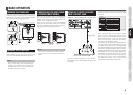
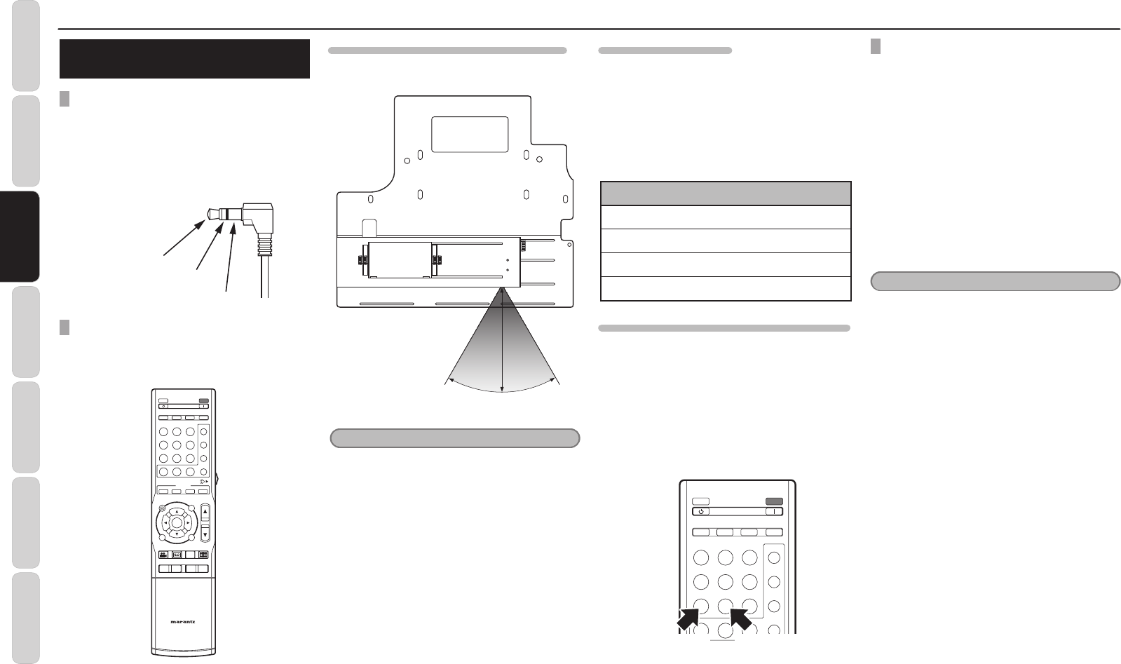
CONCERNING CONNECTORS
AND CABLES
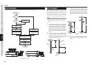
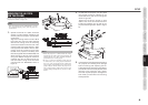
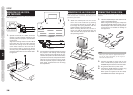
TRIGGER CONNECTOR
The +12 TRIGGER IN/OUT jacks on the LN-11S1A
are used to input/output signals that move the
anamorphic lens into the operating position and
return it to standby position. Either a 3.5-mm
monaural mini-plug or 3.5-mm stereo mini-plug can
be used.
+12V DC
(Trigger Control)
N/C
Ground
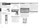
REMOTE CONTROL
A remote controller is not packaged with this unit.
This unit is controlled using the remote controller
supplied with a VP-11 or VP-15 series projector.
INPUT
V-MUTE
ENTER
MENU
ASPECT
FULL
CINEMA
VCR MODE
BLACK LEVEL
PATTERN
BLACK
NOR ZOOM THRU
INFO.
C1 C2 SG1
H1 H2 VG2
A1
A2 RGB G3
STD DYN
I
M
A
G4
THTR
COMP.1 COMP.2 S-VIDEO USER
HDMI 1HDMI 2 VIDEO
AUX 1
BLANKING
AUX 2
RC-11VPS1
REMOTE CONTROLLER
ON
STANDBY
IRIS LAMP
C.TEMP GAMMA
B1 OFFB3B2
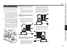
OPERATING RANGE OF REMOTE CONTROLLER
The operating range for a remote controller and this
unit is shown in the figure below.
30˚30˚
5m
Notes:
•Donotallowdirectsunlightorstronglight,such
as from inverter fluorescent lighting, to strike the
remote control receiver. The remote controller
may become inoperational.
•Notethatuseofaremotecontrollermayresult
in the unintended operation of other equipment
controlled using infrared signals.
•Theunitcannotbecontrolledremotelyifthereis
an obstacle between the remote controller and the
remote control receiver.
•Donotplaceobjectsontopoftheremotecontroller.
This may result in continuous depression of
buttons, causing batteries to be consumed.
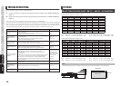
REMOTE CONTROL CODE
Not only is it possible to control this unit using the
remote controller (AUX1 and AUX2) of a VP-11
series or VP-15 series projector, but it is also
possible to control this unit using a programmable
remote controller (such as an RC9001 or RC2001).
Commands used to control this unit are given in the
table on the right. For details, refer to page 5 under
“
ADVANCED OPERATION.
”
RC5
Command
Operation
00 56 15
Moves the anamorphic lens to the
operating position.
00 62 01
Moves the anamorphic lens to the
operating position.
00 56 20
Moves the anamorphic lens to the
non-operating position.
00 62 02
Moves the anamorphic lens to the
non-operating position.
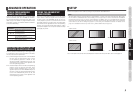
CONTROLLING THE UNIT USING A REMOTE CONTROLLER
This unit can be controlled using a VP-11 or VP-15
series remote controller or programmable re
mote
controller. Refer to Figure 4.
Press the AUX1 button on the VP-11 or VP-15 series
remote controller and the anamorphic lens moves
to the operating position (Refer to Figure 2). Press
the AUX2 button on the VP-11 or VP-15 series
remote controller and the anamorphic lens moves
to the opposite end from the operating position
(Refer to Figure 1).
C1 C2 S G1
H1 H2 V G2
A1
A2 RGB G3
STD DYN G4
THTR
COMP.1 COMP.2 S-VIDEO USER
HDMI 1 HDMI 2 VIDEO
AUX 1 AUX 2
ON
STANDBY
IRIS LAMP
C.TEMP GAMMA
Push to slide in Push to slide out
Figure 4
CLEANING
The anamorphic lens used with this unit is a specially
coated, precision optical product.
If dust attaches to the lens surface, blow it off using
a blower dedicated to cleaning camera lenses. For
dirt attached to the lens, blow away dust attached
to the lens surface using a blower, and gently wipe
the lens using a soft cloth such as a cleaning cloth
or cloth for cleaning eyeglasses. If the
lens surface
is noticeably dirty, wipe the dirt away using a soft
cloth for cleaning lenses dampened with a cleaner
for use with plastic lenses.Then, finish by wiping
the lens in the same manner with a new, soft cloth.
Take care because dirt may re-attach to the lens if
the lens is polished using the same cloth used to
wipe the dirt away.
Note:
Never use alcohol or benzene, thinner, acid/alkaline
cleaning agents, cleaners including polishing
agents, or chemically treated wiping cloth as they
may damage the lens surface.