[~_N_A_M_E_S_A_N_D_F_U_N_C_T_IO_N_S_O_F_P_'A_R_TS
J I
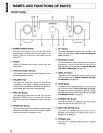
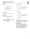
( DISPLAY VOLUME Indicator Volume Display
.....
i2~.
::;
Max
t
t
L HH:.-1
_.
1.
O.5dB Steps
LH~E-1
.....
i.
...
!
'_0'
Turn
the VOLUME knob
on
the
unit to the right, or press the
VOLUME
A button
on
the remote
controller.
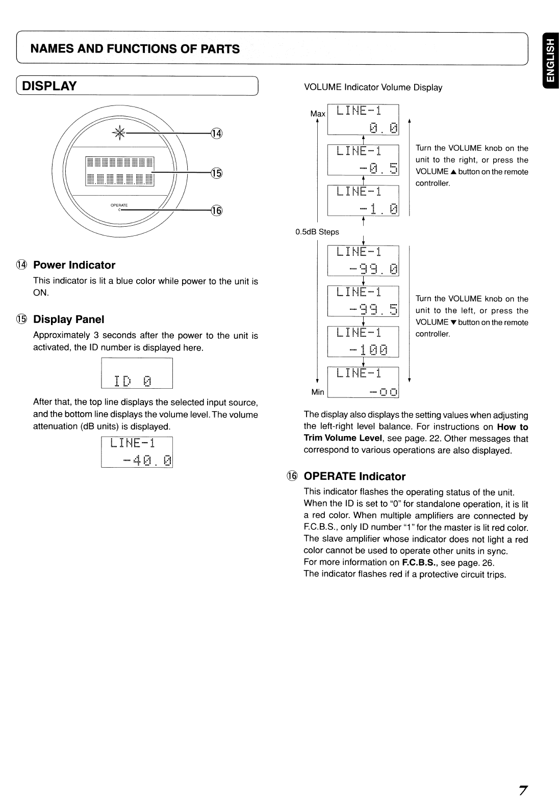
@ Power Indicator
This indicator is lit a blue color while power to the unit
is
ON.
@ Display Panel
Approximately 3 seconds after the power to the unit is
activated, the
ID
number is displayed here.
L I r'iE-1
_.
1
~::~
!::)
LIr··IE-··l
Min
..
- U
!,..!
Turn
the VOLUME knob
on
the
unit to the left,
or
press
the
VOLUME ... button
on
the remote
controller.
After that, the top line displays the selected input source,
and the bottom line displays the volume level.The volume
attenuation (dB units) is displayed.
L
H~E-i
The display also displaysthe setting values when adjusting
the left-right level balance. For instructions
on
How to
Trim Volume Level, see page. 22. Other messages that
correspond to various operations are also displayed.
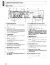
@ OPERATE Indicator
This indicator flashes the operating status of the unit.
When the
ID
is set to "0" for standalone operation,
it
is lit
a red color. When multiple amplifiers are connected
by
F.G.B.S., only
ID
number "1" for the master is lit red color.
The slave amplifier whose indicator does not light a red
color cannot
be
used to operate other units in sync.
For more information on F.e.B.S., see page. 26.
The indicator flashes red if a protective circuit trips.
7


