


10
S
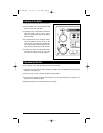
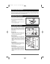
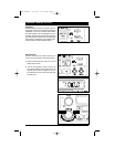
tep 1: The radio chassis is designed to be “Sleeve
Mounted” through a opening in the dashboard
panel. The required opening size is 182mm (7
3/16”) x 84mm (3 5/16”). Cut or engage an opening
in the dashboard to accommodate the mounting
sleeve.
Step 2: If you are replacing an existing factory
installed radio, adapter harnesses might be avail-
able for your vehicle to eliminate the need for cut-
ting your factory wiring. Contact Radio Shack or
other car stereo installation centers for the avail-
ability of these harnesses for your vehicle.
Step 3: Insert the mounting sleeve into the hole in
the dashboard. Bend the metal tabs on the sleeve
to secure the mounting sleeve to the dashboard.
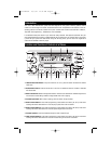
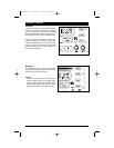
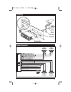
Step 4: Bring all wiring for the connection of the unit
(including the antenna) through the center of the
mounting sleeve. Connect the wiring as follows:
Yellow Wire (W/ Fuse): Connect this wire to a con-
stant +12 volt power source (A power source
that is not controlled by the ignition key).
Orange Wire: Connect this wire to the factory (+)
dashboard lighting circuit that is controlled by
the the headlight switch or dashboard light illu-
mination control switch (Dimmer control). If no
dashboard lighting circuit is available, connect
this wire to the BLUE wire provided on this har-
ness. Note: if this wire is not connected , the
panel lighting on this unit will not light.
Red Wire: Connect this wire to a switched +12 volt
power source (A power source turned on and off
by the ignition key).
Blue Wire: Connect this wire to the (+) power
antenna activation circuit. If no power antenna
exists, tape off the end of this wire. This
connection to prevent shorting out of the unit.
Note: this wire can also be used to activate the
panel lighting on this unit if no dashboard light-
ing circuit is available. (See information for
orange wire connection).
Black Wire: Connect this wire to the frame of the
vehicle (Ground). This wire is the chassis
grounding wire for the unit.
White wire: Connect this wire to the Left Front
Speaker (+) positive terminal or wire.
White Wire with Black Stripe: Connect this wire to
the Left Front Speaker (-) negative terminal or wire.
Gre
en Wire with Black Stripe: Connect this wire to
the Left Rear Speaker (-) negative terminal or wire.
Green Wire: Connect this wire to the Left Rear
Speaker (+) positive terminal or wire.
Gray wire: Connect this wire to the Right Front
Speaker (+) positive terminal or wire.
Gra
y Wire with Black Stripe: Connect this wire to the
Right Front Speaker (-) negative terminal or wire.
Violet Wire with Black Stripe: Connect this wire to the
Right Rear Speaker (-) negative terminal or wire.
Violet Wire: Connect this wire to the Right Rear
Speaker (+) positive terminal or wire.
Note: This unit is designed to connect to (4) four
speakers. If the installation only requires (2) two
speakers , use the White and Gray wire sets to con-
nect the speakers.
WARNING !
Any wires left un-connected must be taped off or
capped off to prevent shorting.
DO NOT! connect speaker ground wires together.
DO NOT! connect speaker ground wires to the
chassis of the vehicle.
DO NOT! connect front and rear speaker wires
together.
FAILURE TO FOLLOW ANY OF THESE WARNINGS
WILL RESULT IN DAMAGE TO THIS UNIT AND IS
NOT COVERED BY ANY WARRANTY.
Installation Procedure
9900 Manual 10/3/02 10:43 AM Page 10