12 13
1. Overview
3. Optional
Accessories
4. Troubleshooting
5. Warranty, Safety
& Specifications
1. Overview 2. Setup & Use
3. Optional
Accessories
4. Troubleshooting
5. Warranty, Safety
& Specifications
2. Setup & Use
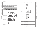
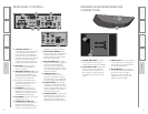
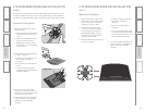
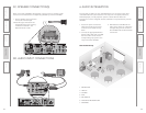
INFRARED SENSOR/RECEIVER (ISR)
CONNECTIONS
1. POWER INDICATOR: This light
will glow blue when the ISR is
receiving power from the CAT 860.
2. A/B IR INDICATORS: These lights
glow when the corresponding
microphone (set to channel A or
B) is turned on and transmitting.
A steady light indicates a strong
signal.
3. SENSOR OUT: Connect the CAT 5
sensor cable to this connection to
send audio from the microphones
to the CAT 860 amplifier.
4. IR EXPANSION: Connect up to
three passive IR sensors (IR-SR70F)
to this connection for larger
classrooms. For more than one
additional sensor a 3-way coax
splitter is required (HS3).
1
2
3
4
RS-232 IN
Front Panel RS-232
Control Select
12
++--
RS-232 IN
Front Panel RS-232
Control Select
12
++--
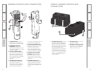
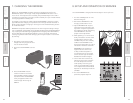
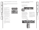
1. CONTROL SELECT: Both
microphone and aux input volume
can be adjusted from the front
panel controls or remotely from
a controller via the RS-232 Serial
Interface. This switch selects either
front panel control or RS-232
control. Front panel controls are
ignored during RS-232 operation.
2. RS-232 IN: A 9 pin connector
to connect the CAT 860 to an
external controller.
3. SPEAKER OUTPUTS (1–4): These
binding post connectors are used
to connect the CAT 860 to the
speakers. Depending on speaker,
all outputs may not be used.
*Note: Wiring to these terminals
should follow the Class 2 wiring
methods as outlined in the
National Electric Code.
4. CHARGERS: These jacks can
be used to charge the optional
LightMic or handheld mic as an
alternative to connecting them to
the REDMIKE cradle charger.
5. DC POWER: Plug the 24 V power
supply into this jack.
6. PAGING INPUT AND ADJ:
Connect the input from optional
PageFirst sensor here when
interface with a buildings paging
system. Use the ADJ control to
adjust the sensitivity if needed.
7. EQUALIZER (4-BAND): Adjust
these controls upon installation to
properly equalize the system to
produce optimium audio quality
from the microphone(s).
8. AUX OUT AND VOL: This jack
sends audio to external equipment
such as an assistive listening
device (Personal FM System) or
recording device. Use the volume
control to set the optimum signal
level for the device.
9. AUDIO INPUTS: These
connections accept an audio
signal from other technology so
all multimedia can be distributed
evenly throughout the classroom.
10. SENSOR INPUT: The infrared
microphone audio from the ISR is
connected to this input via CAT 5
cable. Connect additional sensors
to the CAT 860 to cover large or
odd-shaped classrooms.
11. SENSOR SHORT: This LED glows
red when there is a short in the
ISR or cable. The system will not
operate, but is protected from
damage when the LED is lighted.
REAR PANEL CONTROLS
1
2
3
4
10
11
7
8
9
5
4


