


Krell Current Tunnel 19
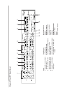
Krell Link Connections and Operation
Krell Link in/out connectors on the KCT back panel allow you to synchronize remote
control operation for systems that include multiple amplifiers and associated
components. When the Krell Link in/out connectors are used, the remote capabilities of
the linked components are controlled from one amplifier or preamplifier, called the
control component. The linked components respond to stand-by and operational mode
commands from the control component via MIDI cables. See Krell Link, on page 32, for
menu options to customize Krell Link operation.
Note
Krell Link uses standard five pin MIDI communication cables, sometimes called MIDI
Plus cables. MIDI cables can be purchased from your authorized distributor or dealer, or
from an audio supply store.
Connecting Components through Krell Link
1. Turn all components off. This ensures all components are synchronized when the
MIDI cable is connected.
2. Select the component to be the control component. The control component must be
in plain view for proper remote control operation.
3. Connect one end of the MIDI cable to the Krell Link out connector (26) on the control
component back panel.
4. Connect the other end of a MIDI cable to the Krell Link in connector (26) on the back
panel of the next component.
5. To link another component, connect another MIDI cable to the Krell Link out
connector on the back panel of the second component. Connect the remaining end of
the MIDI cable to the Krell Link in connector, on the back panel of a third component.
6. Link additional components, if desired.
The components are now ready for operation with Krell Link.
Krell Link Operation
1. When all components are connected, as described above, place each component in
the stand-by mode. This ensures all components are synchronized when signals from
the control component are sent to linked components.
2. Switch the control component to the operational mode from the component’s front
panel power button or through the power key on the remote control. The linked
components simultaneously switch to the operational mode.
An individual linked component can be switched between the stand-by and the
operational modes from its front panel. Switching a linked component temporarily
breaks the chain of linked components. To re-establish linked operation, return all
components to the stand-by mode.