


18 Krell Current Tunnel
Connecting the KCT Preamplifier to Your System
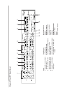
See Figure 2 on page 11
INPUT AND OUTPUT CONNECTIONS
Krell recommends using its proprietary Krell CAST system for unparalleled sonic
performance between the KCT and other CAST-equipped components.
The KCT also offers conventional balanced operation. The circuitry and connections
associated with balanced operation not only can minimize sonic loss but also are
immune to induced noise, especially for installations using long cables.
The XLR pin configuration is described below:
Pin 1 Ground
Pin 2 Non-inverting (0°)
Pin 3 Inverting (180°)
Inputs and outputs are located on the KCT back panel. Maintain the correct left/right
orientation.
IMPORTANT
Connecting non-CAST components to CAST inputs or outputs can damage your
equipment and void your warranty. Do not attempt to alter CAST cable ends or CAST
inputs or outputs. It is electrically impossible to convert CAST input/output chassis
mount connectors for balanced or single-ended operation.
Follow these steps to connect the KCT preamplifier to your system.
1. Neatly arrange and organize the wiring to and from the KCT and all components.
Separate AC wires from audio cables to prevent hum or other unwanted noise from
being introduced into the system.
2. Connect the outputs of your source equipment to the appropriate CAST (20),
balanced (17), single-ended (18) or tape (19) inputs on the KCT back panel.
3. Connect the appropriate main (22 or 23) and zone 2 (24 or 25) outputs on the KCT
back panel to your amplifier(s).
4. Connect the KCT to AC power. Connect the AC power cord to the IEC power
connector (31), then plug the AC power cord into the wall.
KRELL KCT appears in the
front panel display (13), indicating that the preamplifier is initializing. After initializing
is complete, the KCT is in the stand-by mode. The red stand-by LED (2) illuminates.