Using the WP-220E XGA/Audio/Video Line Driver
7
5.1 Installing the WP-220E XGA/Audio/Video Line Driver
To install your WP-220E XGA/Audio/Video Line Driver:
1. Connect the 5 BNC output connectors (each is color-coded: red (R), green
(G), blue (B), yellow (Vertical Sync), and white (Horizontal Sync)) to the
pre-installed wiring in the wall box opening that connects to the XGA
acceptor (for example, a projector).
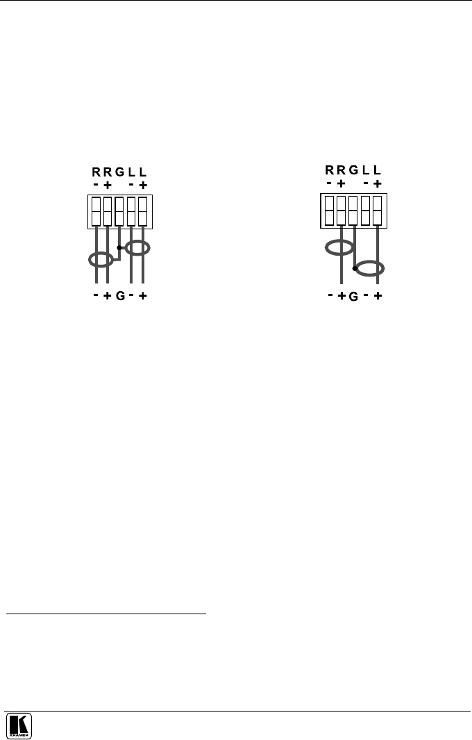
2. Connect the balanced line / PC audio out terminal block connectors (for
example, to power amplifiers) as one of the following:
Figure 7: Connect to a Balanced Acceptor
Figure 8: Connect to an Unbalanced Acceptor
3. Connect your 12V DC power supply to the POWER pins
1
, taking care that
polarity is correct.
4. Connect the wires of the coax cable to the VIDEO OUT pins
2
, taking care
that polarity is correct.
5. Insert the WP-220E directly into the wall box opening, and then mount
the front panel securely using the screws.
5.2 Operating the WP-220E XGA/Audio/Video Line Driver
To operate your WP-220E XGA/Audio/Video Line Driver:
1. Connect an XGA
3
source (for example, a laptop’s graphics card) to the
Input HD15F connector and to the AUDIO Input 3.5mm mini jack, for
example, using a Kramer C-GMA/GMA cable (VGA HD15M +Audio
jack to VGA HD15M +Audio jack)
4
.
1 Connect the wire labeled “+” to the +12V pin, and the wire labeled “–” to the GND pin
2 Connect the composite video wire to the VIDEO pin, and the Ground wire to the GND pin (see Figure 9)
3 Can be used for any RGBHV resolution (for example, VGA, XGA, UXGA and so on)
4 Not supplied. The complete list of Kramer cables is on our Web site at http://www.kramerelectronics.com (click “Cables
and Connectors” in the Products section)


