


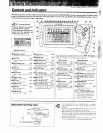


VR-2OBO/VR2080/KRF-V88810/KRF V77710 {E_/K)
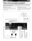
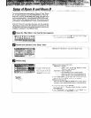
The operations in this section consist of defining the relationship between the input selections displayed on the panel and the _!_ii_;
components connected to the rear panel jacks, _i
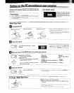
Assigning the connected components to the selected
Generalsetupflow
[] Opening the "Setup"menu
F_Opening the "Setup IR"°menu screen
F1Assigning connected components to the displayed
inputs
E] Completing the assignment of all the connected compo-
fients
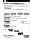
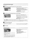
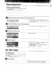
D Select the "Main Menu icon.
_$et#.,_M OdOr TSn dfF'_c Is t pill
Perform icon selection in the "Setup" menu.
O Select the "Stp" icon in the "Main Menu" to display the
"Setup" menu,
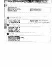
• Tl_e "Setup" menu screen shown on the left appears when the
"Stp" icon is selected,
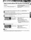
Select the "IR" icon in the "Setup" menu to perform the IR
setup.
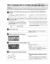
_ Assign the connected components to the inputs selected with the INPUT SELECTOR.
Select an input jack name, consult the Setup Codes chart (on the attached sheet) to find out the setup code corresponding to the
component connected to the selected input, and input the corresponding 4-digit code to assign it to the selected input,
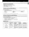
When using digital inputs, perform connection and assignment
taking special care in the relations between the input jacks and
connection curds,
DIGITAL INPUT jack Usable cord connector
VIDEO2 OPTICAL cormector
VIDEO3 OPTICAL connector
VIDE04 COAXIAL connector
CD1 COAXIAL connector
When registering setupcodes for KEI_WOOD audio components
which are connected to this unit by system control cords, use the
following codes to insure proper system controt operation:
Cassette : 7990
Single CD : 8990
Carrousel CD : 8991
200 disc changer CD : 8992
(Multi-room capability CD)
MD : 9990
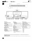
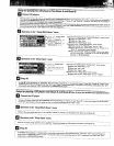
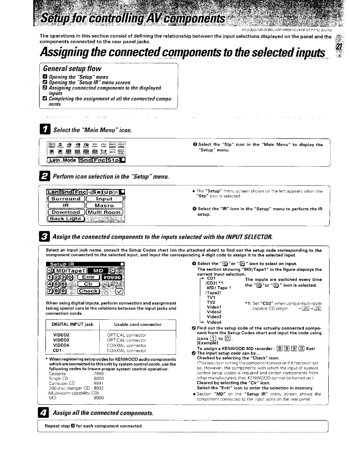
O Select the "_)"or "_ " icon to select an input.
The section showing "MD/Tapet" in the figure displays the
current input selection.
CD1 The inputs are switched every time
(CD2) "1 the "(_ "or "(_ " icon is selected.
MD/Tape 1
(Tape2)
TVl
TV2 * 1: Set "CD2" when _sing a m_ _ti-room
Video1 capable CO player -_] -_._
Video2
Video3
Video4
Q Find out the setup code of the actually connected compo-
nent from the Setup Codes chart and input the code using
icons to
[Examp_el [_"
To assign a KENWOOD MD recorder: [] [] [] [] Entr
E) The input setup code can be,..
Checked by selecting the "Check" icon,
(Ths resu ts in turning the component power on if it has been set
so However, the components -with which the input of system
cor_trol setup codes is required and certain components from
other manufacture{s than KENWOOD cannot be turned on)
Cleared by selecting the "CIr" icon.
Select the "Entr" icon to enter the selection in memory,
• Section "MD" on the "Setup IR" menu screen shows the
component con_ecled [o the nput jacks on the _ear panel.
_l Assign all the connected components,
l Repeat step [] for each component connected,