


50
11 SPECIALIZED COMMUNICATIONS
PREPARATION
1 Connect the transceiver to your personal
computer (via an external TNC or MCP if desired).
• See “COMPUTER” {page 93} and “MCP AND
TNC” {page 95}.
2 Install an appropriate terminal program onto the
personal computer.
• A variety of freeware and shareware programs
can be obtained in various ways. Consult your
reference material or other “packeteers”.
3 Initiate the terminal program and set the following
parameters on the personal computer:
• Transfer rate (TNC/MCP <–> Computer):
9600 bps (default setting)
• Data length: 8 bit
• Stop bit: 1 bit
• Parity: Non-parity
• Flow control: Hardware
4 Press [A/B] to select VFO A or VFO B.
5 Access Menu No. 46 and select the main band or
the sub-band (default) as the data band.
• “TNC” appears on the data band.
• If you are using an external TNC or MCP,
access Menu No. 50E to make this selection.
The default is main band.
6 Access Menu No. 47 and select 1200 bps (default)
or 9600 bps as the transfer rate between TNCs.
• You must select the same transfer rate as the
target station.
• If you are using an external TNC or MCP,
access Menu No. 50F to make this selection.
The default is 1200 bps.
7 Select an operating frequency.
8 Press [LSB/ USB/ AUTO] or [FM/ AM/ NAR] to
select LSB, USB, or FM mode.
9 Access Menu No. 50A and select ON to activate
the DSP packet filter for the main transceiver.
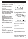
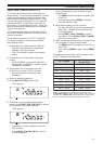
10 Turn the HI/ SHIFT control to select the center
frequency of the packet mode. You can further
select either “NAR” (narrow) or “WID” (wide) for
the receiver filter width by turning the LO/ WIDTH
control.
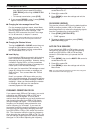
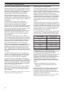
ycneuqerFretneC edoMgnitarepO
zH000113KSP
zH0071)spb0021KSFA(tekcaP
zH0122)spb003KSFA(tekcaP
KSPKSP
Note:
◆
The packet (9600 bps) operation is not affected by the DSP
packet filter settings.
◆
The DSP packet filter works only on the main transceiver.
If you are using an external TNC or MCP, proceed
with the subsequent steps.
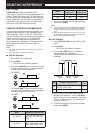
11 Following the instructions provided with your TNC
or MCP, enter the calibration mode so that you
can generate a mark condition.
• The MAIN band LED changes from green (RX)
to red (TX).
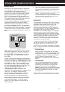
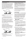
12 Access Menu No. 50B to select the appropriate AF
input level.
• Select a proper input level, so that the ALC
meter reflects within the ALC zone.
13 Exit the calibration mode.
• The MAIN band LED changes from red (TX) to
green (RX).
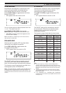
14 Access Menu No. 50C to select the appropriate
AF output level.
• You cannot use the AF control to make this
adjustment.
• If you have selected sub-band in step 5,
access Menu No. 50D instead.
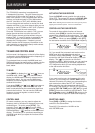
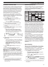
The frequencies (measured in kHz) commonly used
for Packet are listed below:
adanaC/.A.S.U )acirfA/eporuE(1noigeRURA
0381~0081—
5363~02630063~0953
0017~0807—
05101~04101—
5.99041~5904121141~10141,99041~98041
01181~50181—
00112~0901202112~00112
98182~0218200392~00292,05182~02182
08705~00605—
090541~019441—
570144~579044520134~050034
DCD SENSE
You can also select the method for inhibiting the built-
in TNC from transmitting. Access Menu No. 48 and
select one of the two methods. The default is “TNC
BAND”.
TNC BAND:
The TNC does not transmit when signals are present
on the TNC (data) band.
MAIN&SUB:
The TNC does not transmit when signals are present
on the main transceiver or sub-receiver.