


113
21 APPENDIX
COM CONNECTOR
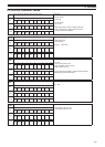
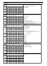
All descriptions in the PC CONTROL COMMAND
TABLE are for the users convenience only.
KENWOOD will not support or warrantee this
documentation in any way.
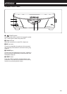
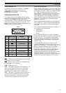
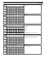
HARDWARE DESCRIPTION
This transceiver uses a full-duplex, asynchronous,
serial interface for communicating through the male
9-PIN RS-232C COM connector. Each data is
constructed with 1 start bit, 8 data bits, and 1 stop bit
(4800 bps must be configured as 2 stop bits). No
parity is used. The pinout and the pin functions of the
COM connector are shown below:
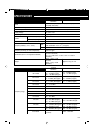
COM
12345
9876
Rear panel view
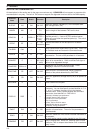
1
2
3
4
5
6
7
8
9
—
Transmit data
Receive data
—
Signal ground
—
Receive enable
Transmit enable
—
—
Output
Input
—
—
Input
Output
—
COM
Pin No.
COM Pin Name
(Ref.: Computer)
Function
(Ref.: Transceiver)
I/O
NC
RXD
TXD
NC
GND
NC
RTS
CTS
NC
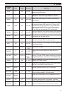
RXD: Transmit data is serial data transferred from
the transceiver to the computer.
TXD: Receive data is serial data transferred from
the computer to the transceiver.
GND: Signal ground pin
RTS: This signal is applied to the transceiver. It is
used to inhibit transmit data from the transceiver
when the computer is not ready to receive data.
Transmit data is inhibited when the level is low.
CTS: This signal is applied from the transceiver. It
is used to inhibit transmit data from the computer
when the transceiver is not ready to receive data.
Transmit data is stopped when the level is low.
CONTROL OPERATION
Most computers handle data in the form of “bits” and
“bytes”. A bit is the smallest piece of information that
a computer can handle. A byte is composed of eight
bits. This is the most convenient form for most
computer data. This data may be sent in the form of
either serial or parallel data strings. The parallel
method is faster but more complicated, while the
serial method is slower and requires less complicated
equipment. The serial form is, therefore, a less
expensive alternative.
Serial data transmission uses time-division methods
over a single line. Using a single line also offers the
advantage of reducing the number of errors due to
line noise.
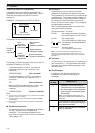
Only 3 lines are required theoretically for control of
the transceiver via the computer:
• Transmit data
• Receive data
• Ground
From a practical standpoint, it is also necessary to
incorporate some means of controlling when this data
transfer will occur. The computer and transceiver
cannot be allowed to send data at the same time!
The required control is achieved by using the RTS
and CTS lines.
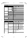
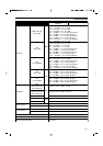
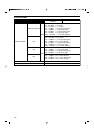
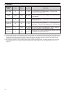
For example, the transceiver is placed into the
transmit mode whenever the character string “TX;” is
sent from the computer. The character string “TX;” is
called a computer control command. It tells the
transceiver what to do. There are numerous
commands available for control of the transceiver.
These commands may be incorporated into a
computer program written in any high level language.
Programming methods vary from computer to
computer; therefore, refer to the instruction manuals
provided with the terminal program and computer.