


47
10 SUB-RECEIVER
ATTENUATOR
The attenuator reduces the level of received signals.
It is useful when there is strong interference from an
adjacent frequency. Since the main transceiver and
sub-receiver share the same antenna for the 144
MHz and 430/ 440 MHz bands, activating the
attenuator function for the sub-receiver also causes
the function to switch ON for the same band of the
main transceiver.
PRE-AMPLIFIER
The pre-amplifier amplifies the level of received
signals. It is useful when the receiving signal is weak.
If there is no strong interference from adjacent
frequencies, switch the pre-amplifier ON to raise the
receiving signal level. Since the main transceiver and
sub-receiver share the same antenna for the 144 MHz
and 430/ 440 MHz bands, activating the pre-amplifier
function for the sub-receiver also causes the function
to switch ON for the same band of the main
transceiver.
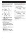
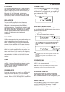
DUAL WATCH
If different frequency bands are set on the main
transceiver and sub-receiver, you can still monitor the
other band activities while transmitting on the TX
band. It is useful that you can still monitor the local
repeater frequency (VHF or UHF band) while you are
working on a DX station on the HF band of the main
transceiver.
If you have the same frequency band (VHF or UHF
band) for the main transceiver and sub-receiver, you
can monitor both frequencies independently at the
same time. However, both receivers will temporarily
mute when you transmit because the transceiver
shares the same 144 MHz and 430/ 440 MHz band
antenna between the main transceiver and sub-
receiver.
SCAN
All types of scanning are also available for the sub-
receiver. However, the operating frequency range is
limited to the sub-receiver’s frequency coverage.
Refer to “SCAN” {page 66} for details on how to
operate the scan function.
NOISE REDUCTION
Since the sub-receiver can receive only in FM or AM
mode, DSP noise reduction 1 (Line Enhanced) is
available to reduce the noise from the receiving
signals. Refer to “NOISE REDUCTION” {page 56} for
details on how to control and adjust the function.
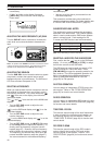
TRANSMITTING
First, confirm that the “ ” icon is on the SUB band
display. Press [SEND] or press and hold Mic [PTT],
then speak into the microphone in your normal tone
of voice. When you finish speaking, press [SEND]
again or release Mic [PTT].
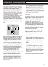
SELECTING A TRANSMIT POWER
You can also adjust the output power for FM mode on
the 144 MHz and 430/ 440 MHz bands when you are
operating the sub-receiver.
1 Press [PWR].
• The current transmit power appears.
2 Turn the MULTI/ CH control counterclockwise to
reduce the power or clockwise to increase the
power.
Note:
◆
The selectable range varies depending on the band and mode
{page 79}.
◆
Output power configuration is also reflected in the main
transceiver.
MICROPHONE GAIN
Access Menu No. 41 and select “LOW”, “MID”, or
“HIGH” for the microphone gain.
Note: When using the optional MC-90 microphone in FM mode,
select “HIGH” microphone gain. Microphone sensitivity is low in FM
mode; this may cause insufficient modulation. For other
microphones, select “MID” or “LOW”.
FM REPEATER OPERATION
You can also configure an independent repeater
offset frequency for the sub-receiver, if necessary.
Refer to “FM REPEATER OPERATION” {page 32} for
details.
REVERSE FUNCTION
Press [TF-SET] to switch the sub-receiver Reverse
function ON (or OFF). “R” appears while the Reverse
function is active on the sub-receiver. Refer to
“REVERSE FUNCTION” {page 34} for details.