KTF-3010/KTF-2010 (En)
5
The system control operations
Remote Control
Lets you operate this unit with the system remote supplied with the amp or receiver.
Automatic Operation (except [XR] equipment)
Automatically switches the input selector on the amp when you operate one of the tuning keys on this unit.
Automatic EON reception
Even if the input selector on the amp is set to a source other than tuner, the amp will automatically switch to tuner when an EON
broadcast you are waiting for is received. When using equipment connected in the [SL16] mode, the amp will switch back to the
original input source when EON broadcast has finished. %
Switching from [SL16] to [XS8]
Use the rear panel switch to switch to the system control [XS8] and [SL16] modes. Do this operation
after completing all connections.
÷ Remove the AC power cord plug from the wall outlet before switching modes.
÷ This operation will not affect items stored in the memory.
SL16 XS 8
j
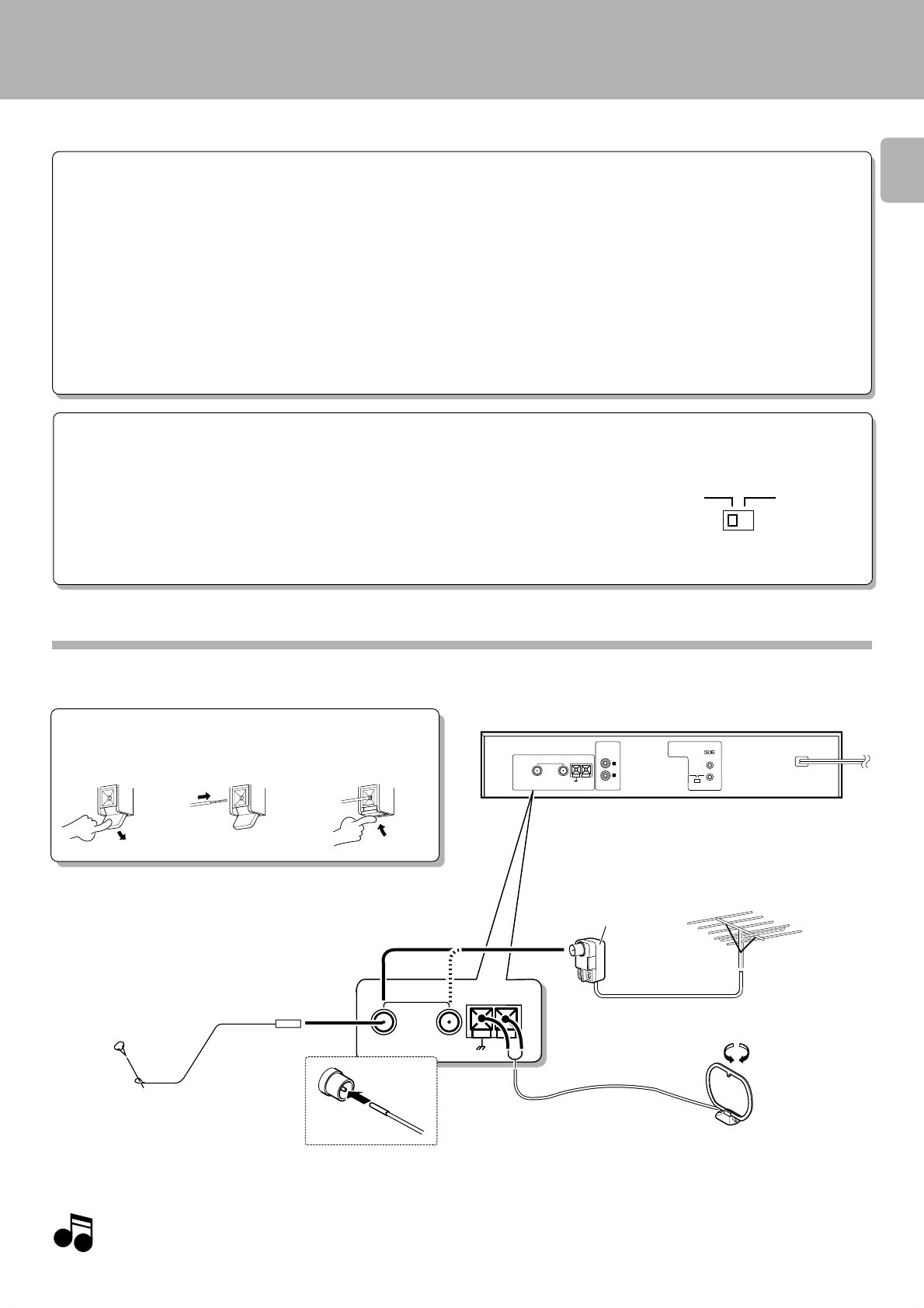
Connection of antenna
AM loop antenna connection
The supplied antenna is for indoor use. Place it as far as possible
from the main system, TV set, speaker cords and power cord,
and set it to a direction which provides the best reception.
Do not plug in the power lead until all connections are
completed.
ANTENNA
GND
FM 75Ω
BA
AM
ANTENNA
GND
AM
FM 75Ω
BA
SYSTEM
CONTROL
ƒ
OUTPUT
R
L
SL16XS 8
Connection method to each antenna terminal
1 Push lever 2 Insert cord 3 Return lever
FM indoor antenna connection
The accessory antenna is for temporary indoor use only.
For stable signal reception we recommend using an
outdoor antenna. Remove the indoor antenna if you
connect one outdoors.
FM outdoor antenna
connection
Lead the 75 Ω coaxial cable connected to
the FM outdoor antenna into the room and
connect it to the FM 75 Ω terminal.
Use a commercially
available antenna
adaptor.
In certain areas, FM broadcast can be received by connecting the antenna cable to a wall antenna terminal (CATV antenna socket, etc.).
If there is only one antenna, connect it to side A of the
antenna terminal.
The figure shows an example for the KTF-3010


