


13
RGB YC
AV COMPU
LINK-
S-VIDEO
SURROUND SPEAKERS SURROUND BACK
VCR STB
COAXIAL
AM LOOP
(
STB
)
RIGHT LEFT SPEAKER
VCR IN
AV
DIGITAL IN
ANTENNA
STB IN OUT
AUDIO IN
VIDEO
RL RL
CENTER
RIGHTSUBWOOFER LEFT SPEAKER
CAUTION:SPEAKER IMPEDANCE 4 16
FM 75
AM EXT
FRONT SPEAKERS
Audio cord
To audio
output
To
S-video
output
S-video
cord
Composite
video cord
To
composite
video output
Audio
connection
Video
connection
VCR
or
RGB Y/C
RGB YC
AV COMPU
LINK-
S-VIDEO
SURROUND SPEAKERS SURROUND BACK
VCR STB
COAXIAL
AM LOOP
(
STB
)
RIGHT LEFT SPEAKER
VCR IN
AV
DIGITAL IN
ANTENNA
STB IN OUT
AUDIO IN
VIDEO
RL RL
MPEDANCE 4 16
FM 75
AM EXT
Audio
cord
To
audio
output
To
S-video
output
S-video
cord
Composite
video cord
To
composite
video output
Video
connection
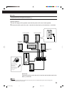
STB (Set Top Box)
Optical
digital
cord
To
optical
digital
output
Audio
connection
or
RGB Y/C
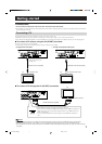
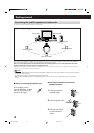
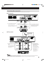
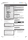
Connecting video components
You can enjoy the picture and sound from VCR and Set Top Box (STB) through the system.
7 VCR connection
1
Connect between video jacks.
Connect S-video cord by
matching the ∞ mark on the plug
to the one on the center unit.
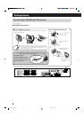
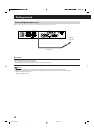
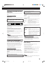
7 STB connection
2
Connect between audio jacks.
Connect the white plug to the
left audio jack (“L”), the red to
the right audio jack (“R”).
Before connecting a
optical digital cord,
unplug the protective
plug.
1
Connect between video
jacks.
Connect S-video cord by
matching the ∞ mark on
the plug to the one on
the center unit.
2 Connect between
audio jacks or optical
digital terminals.
Connect the white plug
to the left audio jack
(“L”), the red to the right
audio jack (“R”).
•Connecting through
optical digital
terminals gives you
better sound.
NOTES:
• Signal input through the S-video jacks is output from both the composite video jacks and S-video jacks, however signal input through the
composite video jacks is not output from the S-Video jacks.
• When connecting through both the composite video jacks and S-video jacks, S-video signal is selected as the video signal.
EN1-16.TH-A75R[B]_f 02.9.5, 4:11 PM13