E6
2. NAMES AND FUNCTIONS OF PARTS
1
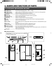
POWER switch................... Turns the main unit power on/off. " | ":ON. " ⅜ ":OFF.
2
POWER Indicator............... Lights up when the POWER switch is turned on. Blinks in case of error during operation.
3
LCD Display Panel............. Shows information using alphanumeric characters.
4
MODE key .......................... Used for LCD display page selection and other operations.
5
SELECT key ....................... Used for switching displayed information and other operations.
6
LOAD/EJECT key............... Opens or closes the mail slot.
7
ENTER key ......................... Used for LCD page selection and other operations.
8
10-key ................................. Used for selecting tray Nos. and changer SCSI ID Nos. for import/export operations.
9
Mail slot .............................. Used for disc insertion/ejection
0
Key cylinder ....................... After completing the door opening mode, insert a key and turn it counterclockwise to open
the door.
!
Rear panel .......................... Opened and closed when installing or replacing drive units.
@
SCSI connector ................. One SCSI connector port system is provided as standard.
#
RS-232C connector ........... 9-pin D-sub connector (plug) for use in maintenance.
$
AC inlet (main unit) ........... Insert the provided power cord and plug the other end of the power cord to a 120 V-240 V, 50
Hz/60 Hz AC power outlet.
%
Side panel .......................... To be removed in servicing.
2-1. Front panel, right side panel, rear panel
ⅥMC-8200LU (MC-8600LU)
Front panel Right side panel Rear panel
9
0
1
POWER
MODE SELECT
LOAD/EJECT
MAIL SLOT
1 2 3 4 5 6 7 8 9 0 E
3
4
8 7
62
5
Control panel : the control panel consist of the keys
2
-
8
and the LCD display screen.
%
!
$
#
@
SCSI-C
MC-8200LU_8600LU INST(E) 04.10.29, 2:07 PM6


