


1-23
KS-LX200R
51
52
53
54
55
56
57
58
59
60
61
62
63
64
65
66
67
68
69
70
71
72
73
74
75
76
77
78
79
80
81
82
83
84
85
86
87
88
89
90
91
92
93
94
95
96
97
98
99
100
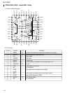
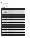
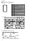
DM0
DM1
ST
LOCAL
MONO
CA-SW1
CA-SW2
CA-SW3
CA-SW4
CA-SW5
VCR-CONT
AFCK
SEEK/STOP
SD
FM/AM
PLL-CE
PLL-DA
PLL-CK
BAND IN
TEL-MUTE
AMP KILL
VSS
DIMMER-IN
DSI
POWER
CD-ON
MUTE
W-LPF1
W-LPF2
W-MUTE
VDD
VOL-DA
VOL-CLK
CF-SEL
NC
LCD RST
LCD-CE2
DMK
TMK
STAGE1
MOTOR
MODE
STANDBY
TEST
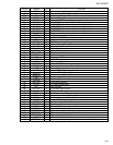
TAPE-IN
SUBMO-
SUBMO+
TAPE-END
KICK
VOICE IN
Door motor negative signal output.
Door motor positive signal output.
Stereo signal input.
Non connect.
Manual ON/OFF select signal output.
DOOR/TRAY open/close detect switch signal input.
DOOR/TRAY open/close detect switch signal input.
DOOR/TRAY open/close detect switch signal input.
DOOR/TRAY open/close detect switch signal input.
DOOR/TRAY open/close detect switch signal input.
Non connect.
AF check output.
AUTO SEEK/STOP select signal output.
Station detector input.
FM/AM select signal output.
Chip enable signal output.
Data output.
Clock signal output.
AM detect signal input.
Telephone.
Non connect.
Connect to GND
DIMMER signal input.
Power save 1.
Power ON/OFF select signal output.
Non connect.
Mute signal output.
Woofer LPF 1 signal output.
Woofer LPF 2 signal output.
Woofer mute signal output.
Power supply.
Data output.
Clock signal output.
CF select signal input.
Non connect.
LCD reset signal output.
Chip enable 2 output.
Motor speed control signal output.
Tray motor control signal output.
Initial setting.
Mecha Motor signal output.
Mecha mode position detection input.
Standby position derection input.
Test terminal
Cassette in detection input.
Sub motor clock direction drive output.
Sub motor clock oppositte direction drive output.
Tape end detection input.
Kick output.
Voice control signal input.
O
O
I
-
O
I
I
I
I
I
-
O
O
I
O
O
O
O
I
I
-
-
I
I
O
-
O
O
O
O
-
O
O
I
-
O
O
O
O
I
O
I
I
I
O
O
I
O
I
Pin No. Symbol I/O Function