


1-22
KS-LX200R
1
2
3
4
5
6
7
8
9
10
11
12
13
14
15
16
17
18
19
20
21
22
23
24
25
26
27
28
29
30
31
32
33
34
35
36
37
38
39
40
41
42
43
44
45
46
47
48
49
50
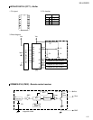
FF/REW
DOLBY
MS-OUT
F/R
HOLD
TRAYCNT
DIMMER-OUT
LCD-POWER
VDD
X2
X1
VSS
XT2
XT1
RESET
SW1
BUS-IN
PS2
CURUISE
RDS-SCK
RDS-DA
REMOCON
AVDD
AVREF0
NC
NC
KEY0
KEY1
KEY2
LEVEL
SQ
S.METER
AVSS
W-VOL
DOT CONT
AVREF
BUS-SI
BUS-SO
BUS-SCK
STAGE2
LCD-DA
LCD-CL
LCD-LEI
BUZZER
E2PR-DA-I
E2PR-DA-O
E2PR-CLK
BUS-I/O
TM0
TM1
Output for input signal level switching for MS.
Dolby on "H" output.
MS output.
Fwd, REV direction switch signal input.
Non connect
Tray light control signal output.
Dimmer signal output.
Non connect.
Power supply terminal.
Connecting the crystal oscillator for system main clock.
Connecting the crystal oscillator for system main clock.
Connect to GND.
Connecting the crystal oscillator for system sub clock.
Connecting the crystal oscillator for system sub clock.
System reset signal input.
Cassette mechanism detect switch.
J-BUS signal cut in input.
Power save 2.
CRUISE signal input.
RDS selial clock input.
RDS data input.
Remove control signal input.
Power supply terminal.
Connect to GND.
Connect to GND.
Connect to GND.
Key control 0 input.
Key control 1 input.
Key control 2 input.
Level meter signal input.
S.quality level input.
S.meter level input.
Connect to GND.
Woofer volume signal output.
Dot contrast signal input.
Power supply terminal.
J-BUS data I/O terminal.
J-BUS data output.
J-BUS serial clock signal I/O.
Initial setting.
Data output for LCD driver.
Clock otput for LCD driver.
Chip enable 1 output for LCD driver.
BUZZER control signal output.
Data input terminal from EEPROM.
Data output terminal from EEPROM.
Data input terminal from EEPROM.
J-BUS I/O signal terminal.
Tray motor negative signal output.
Tray motor positive signal output.
O
O
O
I
-
O
O
-
-
O
I
-
O
I
I
I
I
I
I
I
I
I
-
-
-
-
I
I
I
I
I
I
-
O
O
-
I/O
O
I/O
I
O
O
O
O
I
O
I/O
I/O
O
O
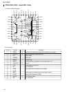
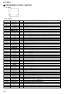
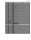
Pin No. Symbol I/O Function
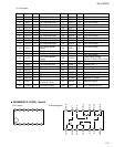
75 ~ 51
1 ~ 25
76
100
~
50
26
~
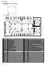
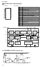
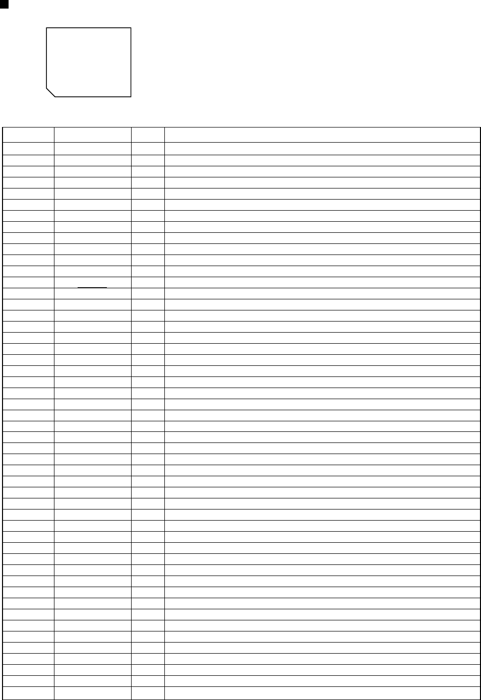
1.Pin layout
2.Pin function
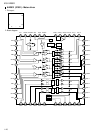
UPD784215AGC113 (IC701) : UNIT CPU