


16
-EN
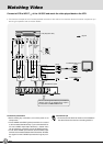
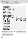
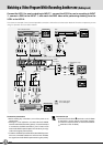
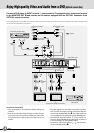
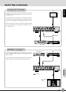
Connect a DVD player to INPUT terminal 4, then connect a TV equipped with a component terminal
to the MONITOR OUT
2 and connect an AV receiver equipped with an OPTICAL connector to an
OPTICAL output connector.
This shows merely an example of connection. Also refer to the Instruction books of the other components you are using for their
connection and operation procedures.
Enjoy High-quality Video and Audio from a DVD (Optical connection)
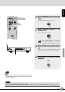
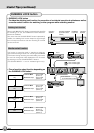
Connection precautions
• Turn off the power to all components before making con-
nections.
• Even when connection using a component video cord out-
put is used, also connect the S-VIDEO and audio cords.
The audio cannot be output unless an audio cord is con-
nected.
JX-S555 Rear panel
DVD Player (Playback deck)
TV
(white)
(red)
(white)
(red)
(white)
(red)
(green)
(blue)
(red)
(green)
(red)
(blue)
(white)
(red)
TV
(Equipped with component terminals)
INPUT
1 24 5
OUTPUT
12
AUDIO
RIGHT
LEFT
VIDEO
12
AUDIO
RIGHT
Cr/Pr
Y
Cb/Pb
Cr/Pr
Y
Cb/Pb
Cr/Pr
Y
Cb/Pb
LEFTOPTICALOPTICALOPTICAL
MONITOR OUT
AUDIO
RIGHT
LEFT
4
Cr/Pr
Y
Cb/Pb
OPTICAL
VIDEO
VICTOR COMPANY OF JAPAN, LIMITED. MADE IN JAPAN
AVIS : RISQUE DE CHOC ELECTRIQUE-NE PAS OUVRIR
WARNING : SHOCK HAZARD-DO NOT OPEN
AV receiver
To
AUDIO
Output
To
S-VIDEO
Output
(white)
(red)
: Signals
(green)
(blue)
(red)
To Component Output To Component Output
To Digital AUDIO Output
To
S-VIDEO
Input
To
AUDIO
Input
(white)
(red)
To
Component
Input
To
AUDIO
Input
(green)
(blue)
(red)
• The video signals from the VIDEO component input at IN-
PUT
4
and
5
are output only at the component video out-
put terminals of MONITOR OUT
2
. The video signals are
not converted into composite video and S-VIDEO signals.
• The OPTICAL signal from INPUT
4
,
5
can only be out-
put to the AUDIO MONITOR OUT OPTICAL connector. It
is not converted to an analog AUDIO signal.
• To watch the video input to INPUT
1
-
3
, also connect a
TV to the MONITOR OUT
1
.