


6
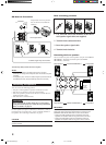
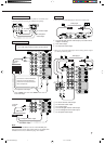
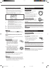
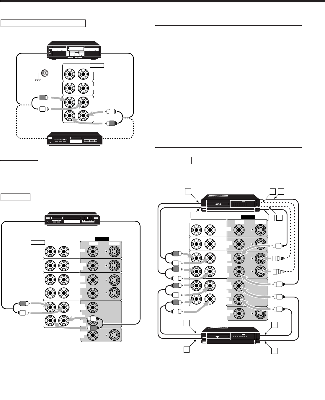
Cassette deck or MD recorder
To audio input
Cassette deck
To audio output
RIGHT LEFT
TAPE
/MD
IN
(PLAY)
OUT
(REC)
CD
PHONO
AUDIO
MD recorder
To audio input
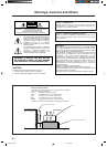
Note:
You can connect either a cassette deck or an MD recorder to the
TAPE/MD jacks. When connecting an MD recorder to the TAPE/MD
jacks, change the source name, which will be shown on the display
when selected as the source, to “MD.” See page 13 for details.
IMPORTANT:
This receiver is equipped with both the composite video and S-video
input/output terminals for connecting video components.
You do not have to connect both the composite video and S-video
terminals.
However, remember that the video signals from the composite
video input terminals are output only through the composite
video output terminals, while the ones from the S-video input
terminals are output only through the S-video output terminals.
Therefore, if a recording video component and a playing video
component are connected to the receiver through the different video
terminals, you cannot record the picture from the playing component
on the recording component. In addition, if the TV and a playing video
component are connected to the receiver through the different video
terminals, you cannot view the playback picture from the playing
component on the TV.
To view and record the playback picture from the video
component connected to the CDR/VCR 2 jacks, you must
connect the TV and the recording video component through the
composite video terminals.
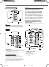
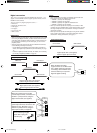
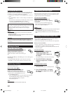
To audio output
VCR
VIDEO
VIDEO S-VIDEORIGHT LEFT
AUDIO
MONITOR
OUT
VCR 1
IN
(PLAY)
OUT
(REC)
IN
(PLAY)
OUT
(REC)
TV SOUND
/DBS
DVD
CDR
/VCR 2
A
B
E
F
DC
A
B
D
E
S-VHS (or VHS) VCR
VHS VCR
Å To left/right channel audio output
ı To left/right channel audio input
Ç To S-video output
Î To composite video output
‰ To composite video input
Ï To S-video input
If your audio components have a COMPU LINK or TEXT
COMPU LINK jack
• See also page 38 for detailed information about the connection and
the COMPU LINK remote control system.
• See also page 39 for detailed information about the connection and
the TEXT COMPU LINK remote control system.
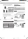
Video component connections
Use the cables with RCA pin plugs (not supplied).
Connect the white plug to the audio left jack, the red plug to the
audio right jack, and the yellow plug to the video jack.
If your video components have S-video (Y/C-separation) terminals,
connect them using S-video cables (not supplied). Connecting these
video components through the S-video input/output terminals will
give you better picture playback (or recording) quality.
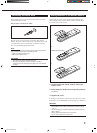
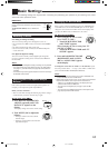
CD recorder
VIDEO
VIDEO S-VIDEORIGHT LEFT
AUDIO
MONITOR
OUT
VCR 1
IN
(PLAY)
OUT
(REC)
IN
(PLAY)
OUT
(REC)
TV SOUND
/DBS
DVD
CDR
/VCR 2
To audio input
To audio output
CD recorder
EN01-09.RX-8000V[J]/f 00.1.12, 0:04 PM6