


41
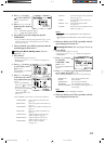
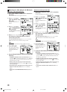
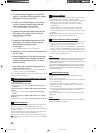
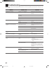
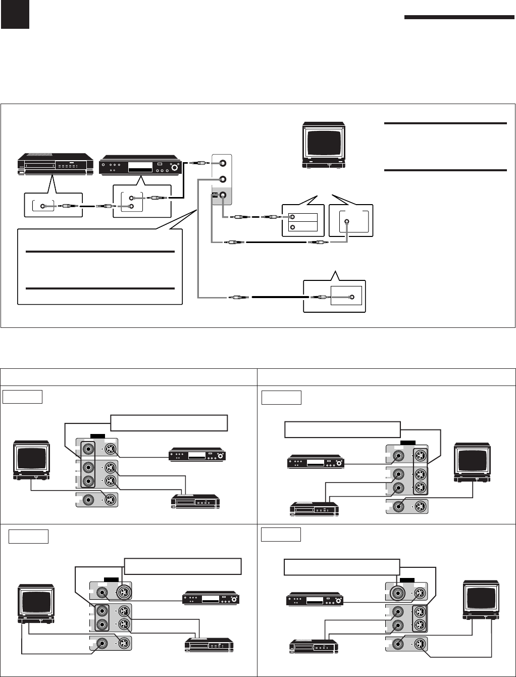
CASE1: If the components are equipped with the S-video
terminals
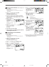
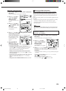
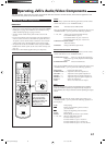
CASE3: If only the VCR is equipped with the S-video
terminal
CASE4: If only the DVD player is equipped with the S-video
terminal
CASE2: If the components are not equipped with the S-
video terminals
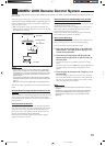
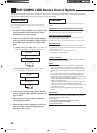
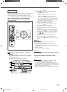
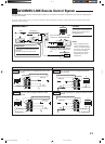
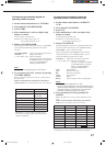
AV COMPU LINK Remote Control System
The AV COMPU LINK remote control system allows you to operate JVC video components (TV, VCR, and DVD player)
through the receiver.
To use this remote control system, you need to connect the video components you want to operate, following the diagrams below and the
procedure on the next page.
CONNECTIONS 1:
TV
If the AV COMPU LINK terminal
on the TV is “RECEIVER/AMP”
If the AV COMPU LINK terminal
on the TV is “AV COMPU LINK
EX”
DVD player
AV
COMPU LINK
RECEIVER/
AMP
AV
COMPU LINK
AV
COMPU LINK
VHS
AV
COMPU LINK
AV
COMPU LINK
EX
RECEIVER/AMP
(VCR)
EX
DVD
IMPORTANT:
Connect to the terminal indicated in the
illustration.
DO NOT connect to the TV terminal.
CAUTION:
The AV COMPU LINK remote
control system cannot control the
DBS tuner connected to the TV
SOUND/DBS jacks.
Notes:
• When connecting only the
VCR or DVD player to this
receiver, connect it directly to
the receiver using cable with
the monaural mini-plugs.
• Refer also to the manuals
supplied with your video
components.
CONNECTIONS 2:
VIDEO
VIDEO S-VIDEO
MONITOR
OUT
VCR 1
IN
(PLAY)
OUT
(REC)
DVD
DVD
S-VHS
VCR
To Video input 1
DVD player
DO NOT use these video terminals.
VIDEO
VIDEO S-VIDEO
MONITOR
OUT
VCR 1
IN
(PLAY)
OUT
(REC)
DVD
DVD
VHS
VCR
TV
To Video input 2
DVD player
DO NOT use these video terminals.
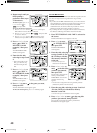
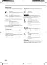
VIDEO
VIDEO S-VIDEO
MONITOR
OUT
VCR 1
IN
(PLAY)
OUT
(REC)
DVD
DVD
VHS
VCR
TV
To Video input 2
DVD player
DO NOT use these video terminals.
To Video input 1
VIDEO
VIDEO S-VIDEO
MONITOR
OUT
VCR 1
IN
(PLAY)
OUT
(REC)
DVD
DVD
S-VHS
VCR
TV
To Video input 1
DVD player
DO NOT use these video terminals.
To Video input 2
VCR
EN41_50.RX-7000V[J]/f 00.1.12, 0:01 PM41