


4
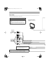
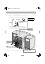
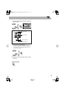
Step
3
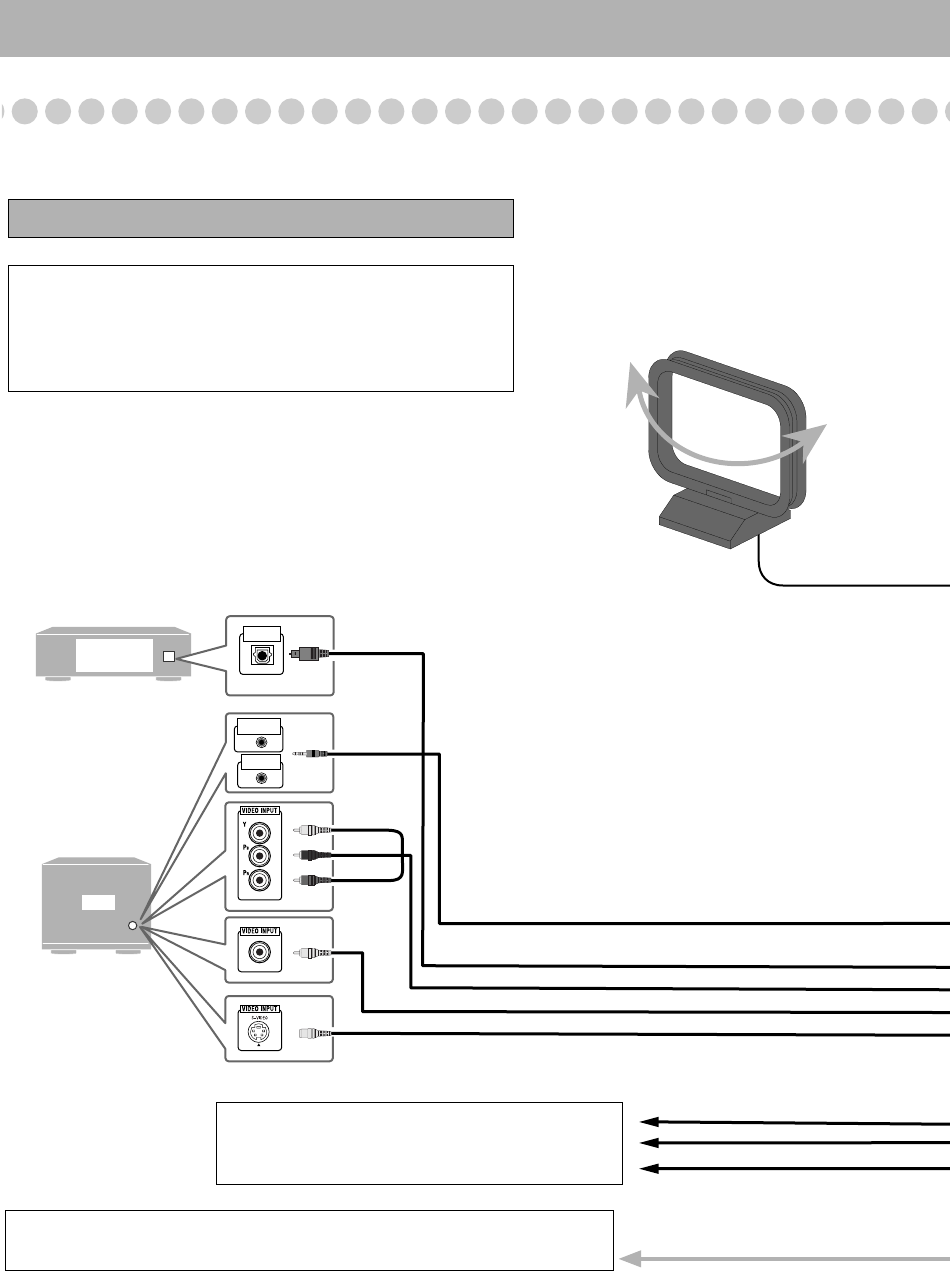
: Hook Up
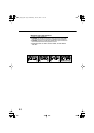
If you need more detailed information, see pages 6 and 7.
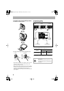
TV
Digital Audio
Equipment
OPTICAL
DIGITAL IN
AV
COMPU LINK II
AV
COMPU LINK EX
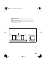
Turn the power off to all components before connections.
Illustrations of the input/output terminals below are typical
examples.
When you connect other components, refer also to their
manuals since the terminal names actually printed on the rear
may vary.
To a wall outlet
Plug the AC power cord only after all connections are complete.
Optical digital cord (not supplied)
Composite video cord (supplied)
Monaural mini plugs (not supplied)
Yellow
S-video cord (not supplied)
Component video cord (not supplied)
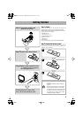
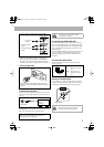
AM loop antenna (supplied)
Turn it until the best reception is
obtained.
Red
Blue
Green
MD recorder,
Amplifier etc.
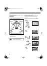
To center speaker/Surround speaker
• See “To connect the speakers” on page 6 and
“Setting the Speakers” on page 8.
MX-JD5[A].book Page 4 Wednesday, June 30, 2004 11:11 AM