


Setup JBL
3-12
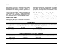
ANLG IN LVL menu level meters indicate input levels for both analog
and digital audio sources. However, ANLG IN LVL menu input level
adjustments only affect 2-channel (or 5.1-channel sources when the
MAIN ADVANCEDANALOG BYPASS parameter is set to OFF)
analog audio sources.
Level meters appear in combinations of green, yellow and red when
the on-screen display is configured for a blue-screen background.
Green indicates low levels; yellow indicates normal levels; and red
indicates the onset of overload. Occasional flashes from yellow into
red are normal peak indicators. Level meters appear in white when
the on-screen display is not configured for a blue-screen
background (see page 3-52).
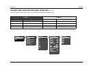
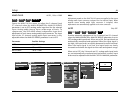
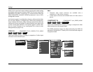
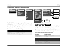
VIDEO IN COMPOSITE-1 TO 2, S-VIDEO-1 TO 3, NONE
Opens the VIDEO IN menu, to assign a composite or S-video input
connector to the selected input.
Note:
• Composite video output connectors are available when a
composite or S-video source is present.
• S-video output connectors are available when an S-video source is
present.
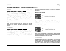
COMPONENT IN COMPONENT 1 to 4, VIDEO, NONE
Opens the COMPONENT IN menu, to assign a component video
input connector to the selected input.
The VIDEO parameter assigns the video selected by the VIDEO IN
parameter (composite or S-video) to be converted and output as
component video.
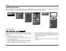
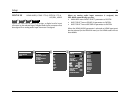
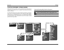
MAIN MENU
MODE ADJUST
AUDIO CONTROLS
SETUP
INPUT SETUP
DVD1
DVD2
LD
TV
SAT
VCR
CD
PVR
GAME
TAPE
TUNER
AUX
SETUP
INPUTS
SPEAKERS
REAR PANEL CONFIG
DISPLAYS
VOLUME CONTROLS
TRIGGERS
LOCK OPTIONS
DVD1 VIDEO IN
COMPOSITE-1
COMPOSITE-2
S-VIDEO-1
S-VIDEO-2
S-VIDEO-3
NONE
DVD1 COMPONENT IN
COMPONENT-1
COMPONENT-2
COMPONENT-3
COMPONENT-4
VIDEO
NONE
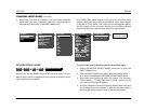
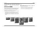
DVD1 INPUT SETUP
NAME DVD1
HDMI IN 1
DIGITAL IN
HDMI
ANALOG IN
NONE
ANLG IN LVL
+0dB
VIDEO IN
NONE
COMPONENT IN
1
2-CH
FILM
D
5.1 FILM
FILM
5.1mc 5.1mc FILM
MAIN ADVANCED
ZONE2 IN DMIX
RECORD IN DMIX
RECORD ADVANCED
INPUTSSETUP
DVD1
VIDEO IN
INPUTSSETUP
DVD1
COMPONENT IN