


SDP-40HD Basic Operation
2-7
Component video output is available when a component,
composite, or S-video source is present.
Note:
The video outputs that incorporate the on-screen display (OSD) can
also display the two-line status. However, to view the two-line status
through the component output, it must be configured to convert and
display composite or S-video. See “COMPONENT IN” on page
page 12.
CAUTION!
Never make or break connections to the SDP-40HD unless
the SDP-40HD and all associated components are powered
off.
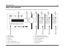
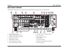
7 ZONE 2 AUDIO OUTPUT CONNECTORS
Provides analog audio output from Zone 2. Two sets of stereo
connectors are available. The connectors labeled “Fix” pass audio
at fixed output levels. The connectors labeled “Var” pass audio at
variable output levels and include a built-in volume control.
8 RECORD ZONE VIDEO OUTPUT CONNECTORS
Provides video output from the Record Zone. Two composite video
connectors and two S-video connectors are available. These
connectors can be used to connect a monitor or video recording
device.
9 IR IN CONNECTOR
Accepts input of IR signals from infrared distribution equipment.
One 3.5mm jack that accepts a stereo plug (Tip/Ring/Sleeve
connection) or mono plug (Tip/Sleeve connection) is available.
10 REMOVABLE ACCESS PANEL
Covers the expansion slot, which is reserved for emerging
technologies.
11 POWER SWITCH
The Power Switch disconnects power from the AC Input Connector
(12) to the product. The I and O positions represent “on” and “off”
status, respectively. When the SDP-40HD is powered on, the front-
panel Standby button or remote control On button can be used to
activate and deactivate standby mode. When the SDP-40HD is
powered off, standby mode is not available.
12 AC INPUT CONNECTOR
Provides power to the SDP-40HD through the supplied power cord.
13 RECORD ZONE AUDIO OUTPUT CONNECTORS
Provides analog and digital audio output from the Record Zone.
Two stereo connectors labeled Audio L/R output analog audio. The
connector labeled “Fix” passes audio at a fixed output level. The
connector labeled “Var” passes audio at variable output levels and
includes a built-in volume control. Two S/PDIF connectors (one
coaxial and one optical) output digital audio.
These connectors can be used to connect a recording device. When
the Record Zone audio output connector labeled Var is connected
to a recording device, you should set the volume to +0dB to
achieve appropriate recording levels. See “REC PWR ON” on page
page 55 for more information.