


Basic Operation JBL
2-8
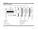
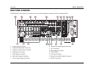
REAR-PANEL OVERVIEW (continued)
14 RS-232 CONNECTORS
The RS-232 serial connector (1) is used to perform backup and
restoration of configuration files and flash memory software
upgrades. The RS-232 connector (2) is capable of supporting
future developments.
15 MAIN ZONE AUDIO OUTPUT CONNECTORS
Provides analog audio output from the Main Zone. Ten connectors
labeled Front L/R, Center, LFE, Subwoofer L/R, Side L/R, and Rear L/
R are available. Two connectors labeled Aux L/R are provided for
future expansion.
16 MICROPHONE INPUT CONNECTORS
Provides microphone input. Four 3.5mm Tip/Ring/Sleeve
connectors are available.
17 TRIGGER OUTPUT CONNECTORS
Provides 12V DC output to control connected components. Three
trigger output connectors are available on a removable terminal
block. The PWR connector – the power trigger output connector –
cannot be configured. It is activated when the SDP-40HD is
activated, and deactivated when the SDP-40HD is deactivated. The
trigger output connectors (1) and (2) can be configured for remote
or program operation.
18 DIGITAL AUDIO INPUT CONNECTORS
(AES/EBU & S/PDIF)
Provides digital audio input to all zones. One AES/EBU (XLR), six S/
PDIF coaxial (RCA), and six S/PDIF TOSLINK
TM
optical input
connectors are available. These connectors are compatible with
PCM (44.1, 48, 88.2, and 96kHz), Dolby Digital, and DTS-ES
sources. These connectors are not compatible with MPEG or MP3
sources.
19 BALANCED AUDIO OUTPUT CONNECTORS
Provides balanced analog audio outputs in the Main Zone and
Zone 2. Ten connectors labeled Front L/R, Center, LFE, Subwoofer
L/R, Side L/R, and Rear L/R are available in the Main Zone. The
connectors labeled Aux L/R are provided for future expansion. Two
connectors labeled Zone 2 L/R are available for Zone 2.
20 ANALOG AUDIO INPUT CONNECTORS
Provides analog audio input. Eight stereo analog audio input
connectors labeled 1 to 8 are available. Connectors labeled 6, 7
and 8 can be configured as 5.1-channel connectors.
When a 5.1-channel analog audio source is present in the Main
Zone input signals are sent to the Main Zone audio output
connectors as indicated in the table on the following page. If the
ANALOG BYPASS is ON, a 5.1-channel analog source is present in
the Main Zone, and the INPUT SETUP menu ZONE2 IN or RECORD
IN parameter is set to DMIX, only the (L) and (R) input signals are
sent to the Zone 2 or Record Zone audio output connectors.