- 17 - SDEC -X000 DACS Calibration Manual v1.0.doc
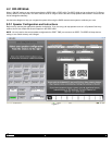
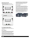
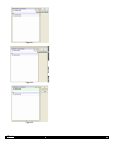
8.2.2 Dipole Surrounds
Regardless of model there is one standard for phase
configuration of Dipole surrounds.
Figure 16.
8.2.3 Direct Radiating Point Source
Surrounds
Figure 17.
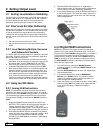
8.3 Using the Phase Tester
The Galaxy Audio phase tester consists of two battery
operated instruments, Cricket-S is the "sender", and Cricket-R
is the "receiver".
8.3.1 Cricket-S
The sender generates a short duration, positive polarity pulse.
This is applied to the power amplifier input which drives the
loudspeaker being tested. Coincident with the generation of
each pulse, a green LED is illuminated. Three output
connectors are located on the rear panel. Line level male XLR,
line level female ¼" phone jack and a speaker level female ¼"
phone jack. A female XLR to RCA adapter cable is provided in
the kit. Plug this cable into the XLR connector and use it to
connect the sender to each channel for test. On the front panel
are two slide switches and a pulse indicating LED. Slide the
ON/OFF switch to the ON position and the output selector to
the LO position. You should now hear pops at one second
intervals from the speaker under test. If a higher level is
required, set the output selector to HI.
8.3.2 Cricket-R
The receiver contains a microphone and phase analysis
circuitry. Positive polarity is indicated by a green LED, negative
by a red LED. Two input connectors and the microphone are
located on the rear panel. There is also a switch marked
"CON" (continuity) and "POL" (polarity). Place this switch in the
"POL" position. On the front panel are two slide switches, a
rotary gain control and the two phase indicating LEDs. Slide
the right side switch to the ON position and place the left side
switch in the MIC position. Now move the receiver’s
microphone toward the speaker being tested. W hen you are
within three to six inches of the speaker you should begin to
see a polarity indication. Adjust the gain control until a
consistent indication of phase is realized.


