


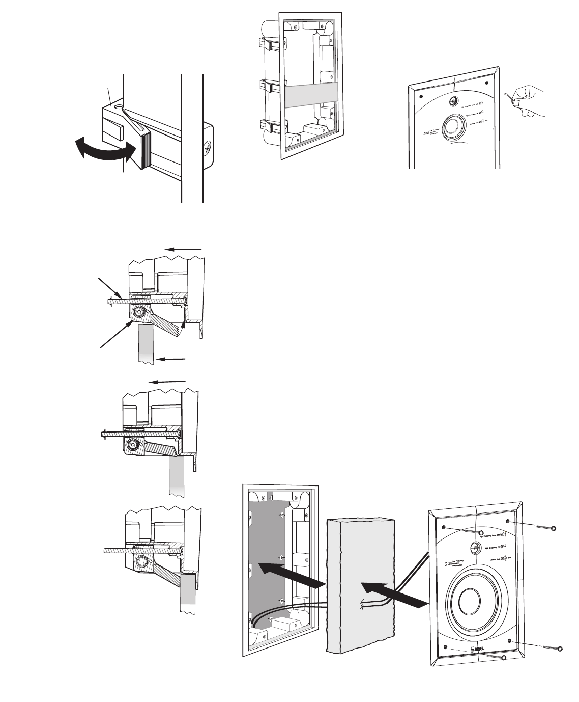
7. Be sure to run the speaker wire in
t
hrough the rear opening before
r
einstalling the baffle assembly.
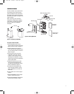
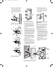
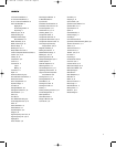
8. Insert the mounting frame into the
cutout until the clamps snap into
p
lace.
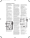
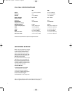
Figure 13: Clamp Close-Up
Figure 14: Clamp Mechanism
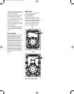
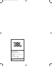
Figure 15: Frame Alignment Tool
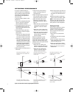
9. Insert the frame alignment tool
horizontally into the center of the
frame. This tool functions as a
frame spreader, while the clamps
are being tightened, as shown in
Figure 15.
10. Starting from the lower right corner
and working in a diagonal torque
sequence, use a power screwdriver
to tighten each of the clamp screws
(only until almost snug). If needed,
adjust the mounting frame so it is
level and centered in the cutout.
11. Perform a final torque sequence.
Hand-tighten frame screws and
check each screw at least twice to
make sure they are fully tightened
to prevent rattles.
12. Remove the frame alignment tool.
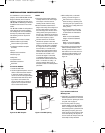
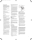
13.
Place the included fiberglass insula-
tion in the back of the mounting
frame, as shown in Figure 16. Cut an
“x” into the insulation and thread
the wire(s) through.
14. Make speaker wire connections.
R
efer to the Making Connections
s
ection on page 11 for instructions.
15. Slide the baffle into place in the
mounting frame.
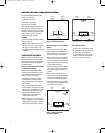
Figure 17: Tighten Allen Screws With
Allen Key Wrench
NOTE:
Be sure that the speaker wires
are clear of the woofer basket and not
too close to the woofer cone. Make
sure the wires are not pinched
between the baffle and the mounting
frame. Refer to Figure 16.
16. Use the spacer shim to center the
baffle inside of the frame while
securing with four 10-32 x 2-1/4-inch
screws. Loosely tighten the screws
while using the spacer on the bottom
side. Remove spacer and gauge the
other three sides before starting
final torque sequence. Proper cen-
tering of the baffle is critical to the
grille fitting properly.
17.
Use the included 5/32-inch Allen key
to tighten until snug, as shown in
Figure 17.
F
igure 17:
Tighten Allen screws with Allen key wrench
Mounting Frame
Clamp
Frame
Alignment
T
ool
Figure 15:
Frame Alignment Tool
A
C
lamp
Screw
B
C
Insert frame into
wall opening
Wall
Figure 14:
Clamp Mechanism
Note how the clamp
springs open
CLAMP
F
igure 13: Clamp Closeup
10
Figure 16: Install the Insulation and Baffle
Baffle
Assembly
Thread Speaker Wires
Fiberglass Insulation
Allen Head
Screws
Figure 16: Install the Insulation and Baffle
P81, P941 OM 2/18/05 10:55 AM Page 10