


•
Two high-grade neodymium magnets
p
laced inside the voice coils for opti-
m
al magnetic shielding
•
Symmetrical Field Geometry (SFG
™
)
design for low overall distortion
•
1-1/2-inch (38mm) voice coil wound
on a fiberglass bobbin for high-power
handling and low distortion
•
Copper cap stabilizes inductance and
controls flux modulation, dramatically
reducing distortion
•
Optimized and shielded magnetic cir-
cuits to minimize harmonic distortion
and prevent video monitor interfer-
ence
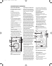
FILTER NETWORK
Optimizes loudspeaker on- and off-axis
response with a high-order filter at
2.8kHz for the P81, and high-order
filters at 300Hz and 2kHz for the P941,
helping to ensure smooth octave-to-
octave balance and timbral accuracy.
Gold-plated binding posts accommo-
date heavy speaker cables, while
separate Low-Frequency Boundary
Compensation, High-Frequency Level,
High-Frequency Tilt and Listener Axis
controls provide precise balance to
compensate for less-than-ideal listen-
ing room acoustics and loudspeaker
placement.
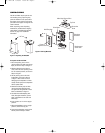
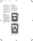
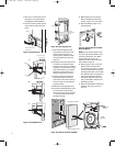
INPUT PANEL
N
umber 1 in Figure 5 corresponds to
the numbered item below.
1. Input Connectors
Provide input connections from the
associated power amplifier/receiver(s).
One positive (+) gold-plated binding
p
ost and one negative (–) gold-plated
binding post are available. Refer to
the Making Connections section on
page 11 for additional information.
Figure 5: Rear of P81 and P941
7
P81
P941
Figure 5: Rear of P81/P941
P81, P941 OM 2/18/05 10:55 AM Page 7