


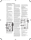
Painting the Grille
F
or best results, it is recommended
that the grille be painted with a spray
applicator to enable the paint to be
evenly applied to the inside edges of
t
he grille’s perforations.
The following items are required to
paint the grille:
•
the grille (included)
•
replacement scrim cloth (included)
•
s
pray paint
•
paint thinner (and cloth)
•
r
ubbing alcohol (and cloth)
•
white or neutral color water-based
primer
•
masking tape
•
spray adhesive
CAUTION: The grille must be painted
before it is attached to the frame.
To Paint the Grille:
1. Remove the grille from the grille filler.
2. Remove the scrim cloth on the inside
surface of the grille. If necesssary,
slightly peel up the lower inside
edges of the black felt strips to
remove the scrim.
3. Inspect the inside surface of the
grille to ensure that there are no
remnants of the scrim cloth. If neces-
sary, remove any remnants by rub
-
bing with a cloth dampened with
paint thinner.
4. Clean the front grille surface with a
cloth dampened with rubbing alcohol.
5.
Apply masking tape over the black
felt strips around the grille perimeter
to shield them from paint. Be sure to
mask only the felt and not the outer
metal edges of the grille, so that they
will be painted.
6. Apply one coat of the primer and let
it dry.
7. Thin the paint before application.
8. Apply one to two coats of spray
paint. Use a varied spraying angle
when spraying, to ensure paint is
applied to the inside edges of the
grille perforations.
After the paint is dried, install the
replacement scrim cloth, if desired.
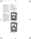
To Attach the Replacement Scrim Cloth:
1
. Place the grille face down on a soft
surface.
2. If paint thinner was used to remove
s
crim remnants, apply a light coating
of a spray adhesive to the inside
grille surface. Avoid spraying adhe-
sive onto the felt strips. If too much
adhesive is used, it could wick into
t
he cloth and degrade the sound.
3. Place the replacement scrim cloth
in the grille with the cardboard side
facing upward (so that the cardboard
is not visible through the front of the
grille).
4. Tuck the outer edges of the scrim
cloth cardboard frame under the
black felt strips and gently smooth
the scrim cloth over the grille surface
to remove any wrinkles.
Attaching the Grille to the
Frame
To Attach the Grille:
1. Line the grille up to the frame and
press the grille in only partially at
first.
2. Push gently at multiple points around
the outer edges to slowly ease it into
position.
NOTE: Configure the four front-panel
controls and experiment until optimal
results are achieved, before installing
the grille.
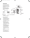
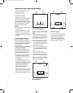
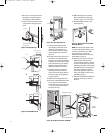
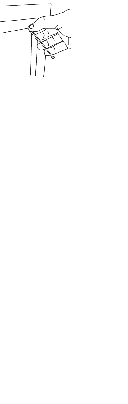
Grille Removal
To Remove the Grille:
1.
Insert the small end of the included
1/16-inch Allen key into one of the
metal mesh holes in the top corner
of the grille, as shown in Figure 20.
2. With the end of the Allen key in the
grille hole approximately 1/8 inch,
with thumb and forefinger close to
the grille, pull up on the Allen key to
wedge it into the grille hole.
3. Gently pull the Allen key to partially
pop out the corner of the grille.
4. Repeat Steps 1 to 3 for the other top
corner.
5.
Apply Steps 1 to 4 for the bottom
corners.
6. When all corners are partially
popped out, the grille can easily
be removed.
Figure 20: Removing the Grille
C
AUTION:
D
o not attempt to pry the
grille out using the Allen key (or any
other object) as a pry bar against the
plastic frame.This will cause damage
to the frame and mar the paint.
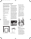
Speaker Frame Removal
To remove the speaker frame from wall
opening:
1. Fully unscrew all of the clamps
around the speaker housing. The
clamp screws have an acorn nut
attached on their end to prevent
accidental disassembly.
2. Move the speaker housing away
from the wall enough to wedge your
hand behind and pinch a clamp shut.
3. While the clamp is shut, work the
speaker housing forward enough to
catch the shut clamp in the wall
opening.
4.
W
ork around the perimeter
, carefully
closing each clamp and then slowly
pull the speaker housing from the
wall.
LOUDSPEAKER VOLUME LEVELS
High-order filters include steep cut-offs
to reduce potential damage from “out-
of-band” frequencies. Combined with
carefully selected transducers and fil
-
ter network components, this approach
helps the P81/P941 to maintain its per-
formance under extreme operating
conditions.
However, all loudspeakers have limits
when it comes to continuous playback.
To extend these limits, avoid playback
at volume levels that distort or strain
sound.
Grille
1/16-inch Allen key
Frame
Figure 20: Removing the Grille
13
P81, P941 OM 2/18/05 10:55 AM Page 13