


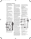
The P81 and P941 feature gold-plated
b
inding posts that allow for two meth-
o
ds of connecting the speaker wires.
CAUTION: Never make or break con-
nections unless all system components
are powered off.
Before making connections, note the
f
ollowing:
•
Make all connections observing the
proper polarity, positive-to-positive (+)
and negative-to-negative (–). Connec-
t
ions that do not observe the proper
polarity will cause poor stereo imag-
ing and diminished bass response.
With the advent of multichannel sur-
round systems, maintaining proper
polarity remains equally important to
preserve the correct ambience and
directionality of the program material.
•
Use high-quality loudspeaker cable
with a maximum total loop resistance
of 0.07 ohms or less (for each wire
run). Refer to the table below to
determine the appropriate maximum
wire gauge.
•
All in-wall speaker wires must be UL
listed for use in in-wall applications.
CAUTION: Be sure to comply with local
wiring codes. JBL is not responsible for
any damage or injuries that may result
from faulty wiring.
Maximum Wire Gauge
Gauge Length Length
(AWG) (Feet) (Meters)
6
87 27
7 69 21
8 58 18
9 43 13
10 34 10
11
27
8
12 22 7
13
17 5
14 14 4
15 11 3
16
9
3
17 7 2
18 5 2
NOTE: High loop resistances that
exceed 0.07 ohms (for each wire run)
will cause the filter network to mis-
terminate, resulting in considerable
degradation of sound quality.
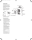
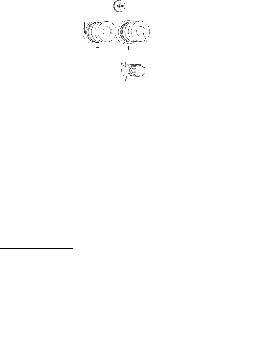
Figure 18: Making Connections
•
Contact an authorized JBL dealer for
information about the suitability of
power amplifier/receiver components
before connecting the P81 or P941
to the associated power amplifier/
receiver.
•
Review the owner’s manuals for asso-
ciated audio components to deter-
mine their connection procedures.
Connections are made between one
pair of P81 or P941 input connectors
and one amplifier/receiver output
channel, as described below.
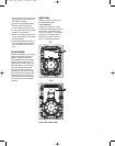
To Make Connections:
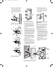
1. Loosen the terminal connectors by
hand (counterclockwise) on the
speakers’ positive (+) and negative
(–) binding posts until the holes in
their threaded posts are visible.
2.
Insert the stripped ends of the
wires through the holes, as shown
in Figure 18.
3. Retighten the connectors by hand
(clockwise) to secure the wire. Be
sure no stray strands of wire from
one binding post touch the other
binding post, as this will short-out the
signal and may damage the amplifier.
4. In the manner described above, con-
nect one pair of loudspeaker wires
to the P81 or P941 input connectors.
Then connect the same pair of loud-
speaker wires to the desired amplifier/
receiver output channel.
5. Repeat Steps 1 to 4 to connect the
s
econd P81 or P941 to a separate
a
mplifier/receiver output channel.
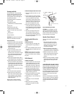
An alternative connection method,
instead of those described in Steps 1 to
3
, is to attach standard banana plugs to
t
he speaker wires and plug them into
the ends of the speaker connectors.
The hole in the center of each collar is
i
ntended for use with banana-type con-
nectors. To comply with European CE
certification, these holes are blocked
with plastic inserts at the point of
m
anufacture. The use of banana-type
connectors requires the removal of
the inserts. Do not remove these
inserts if you are using the product
in an area covered by the European
CE certification.
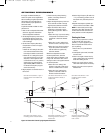
If using a back box or if limited by
installation depth, the banana plugs
can also be inserted through the sides
of the binding posts. See Figure 18.
I
nsert Speaker Wire
Terminal Connectors
Insert
Banana Plug
h
ere if desired
E
xposed Binding Post (connector removed)
B
inding
Post
Figure 18: Making Connections
11
MAKING CONNECTIONS
P81, P941 OM 2/18/05 10:55 AM Page 11