


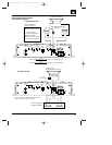
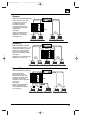
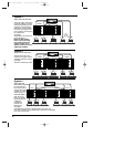


Additional System
Configurations for Add-On
or Upgrade
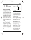
The features and capabilities of the
GTS100 provide tremendous system
design flexibility. The diagrams on the
following pages illustrate some of the
system possibilities. They are in order
of increasing complexity, showing the
way a system may be upgraded in
logical steps. Although the systems are
shown using speaker-level connection
from the head-unit, they may be built
using any combination of speaker or
preamp level inputs, depending on the
capability of your head unit. (See
pages 25-26.)
24
ence as a result of its switch-mode
operation. Although this is internally
filtered and shielded by the GTS100
chassis, some unusually sensitive
installations may pick up switching
noise, especially when listening to weak
AM radio stations. If this unusual situa-
tion occurs, one of the following installa-
tion corrections will typically eliminate
the problem. 1) Relocate the amplifier
to a position farther away from the radio
or radio antenna. 2) Move the electrical
ground of the head unit and/or amp to a
different point on the vehicle’s chassis.
3) Keep the amplifier power supply
wiring away from the radio or antenna
wiring. 4) Wrap the +12 volt power sup-
ply wires for the radio/tape deck with
metallized shielding tape or ground
braid and ground the tape to the chas-
sis of the vehicle.
Maintenance
The GTS100 does not require any regu-
lar maintenance. Periodically checking
the main power supply and grounding
points and terminal connections is
advisable. Be sure the connections are
solid and corrosion-free. Loose or cor-
roded connections can cause annoying
intermittent noise or unusual opera-
tional problems. Do not allow dust to
accumulate on the amplifier heat sinks.
It will reduce the amplifier’s ability to
dissipate heat. Occasional vacuum
cleaning will prevent dust accumulation.
JBL 1394 Manual 7/17/98 11:49 AM Page 24