


11
POWER
Power Indicator
L
R
LINE
IN OUT
NOM
MIN MAX
GAIN
INPUT MODE
STEREO
CROSSOVER
OFF HIGHRL
+
R
LOW
+
R
-
+
L
-
+
R
-
+
L
-
SPEAKER
OUTPUTS
SPEAKER
INPUTS
BRIDGED
FUSE 20A
POWER
BAT(+) REM GND
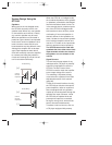
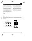
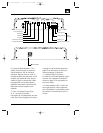
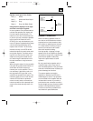
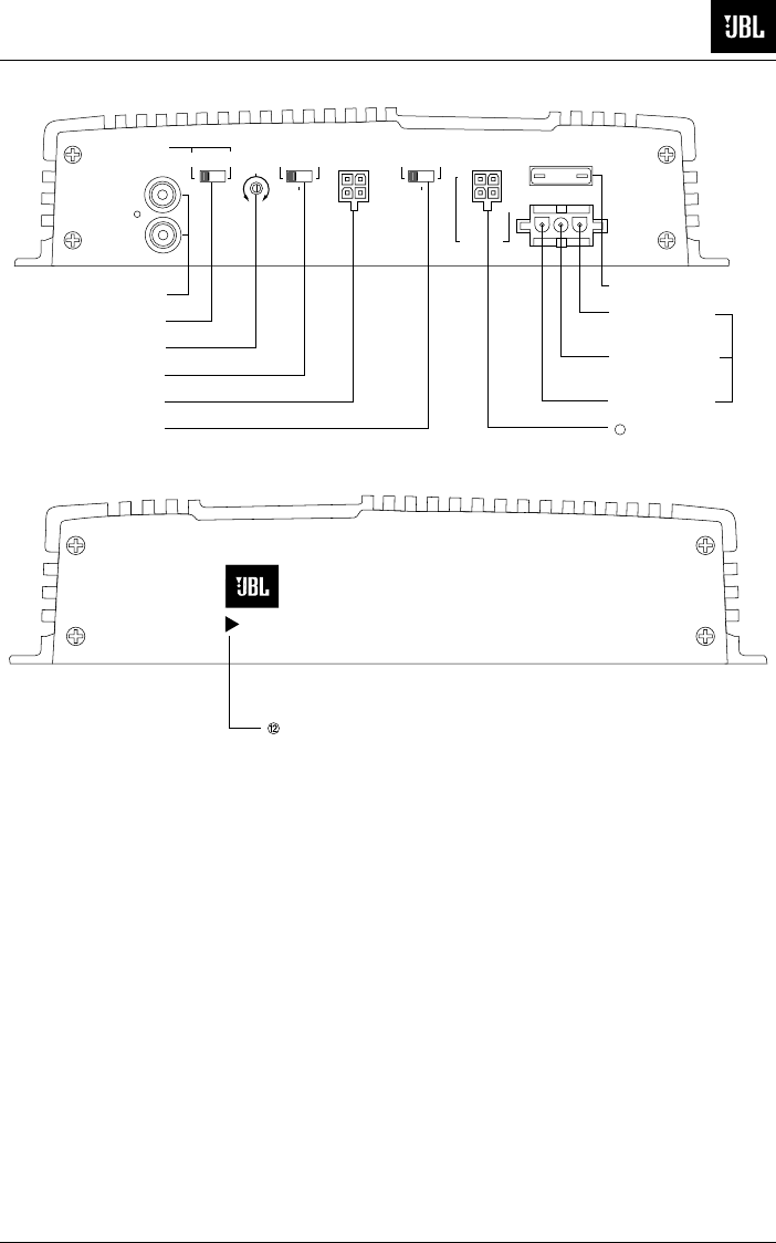
➀ Line Level RCA Inputs
➁ Line Selector
➂ Gain Control
➃ Input Mode
➄ Speaker Input Connector
➅ Crossover Mode Selector
20A
Power
Connector
➆ Fuse
➇ Battery Ground
➈ Remote Turn-On
➉ Battery (+) In
➉ Speaker Output Connector
11
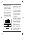
6. Crossover Mode Selector
– This
switch controls the built in crossover.
Set the switch to “Off” for full band
operation. Set this switch to “Low” to
activate the 80Hz low pass filter on the
amplifier (for subwoofer use). Set the
switch to “High” to activate the 100Hz
high pass filter for use with satellite
speakers. Note that the filter does not
affect the line level outputs on the
amplifier.
7. Fuse
– 20 Amp ATC type Fuse.
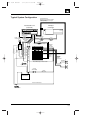
8., 9., 10. Power Connector
–
Connection for included power wire har-
ness. See “Power Supply Connections”
on page 14 and the wiring diagram on
page 13 for information on wire color
codes and proper connections.
11. Speaker Output Connector
–
Connection for included speaker output
harness. See “Speaker Connections”
section on page 17 for information on
wire color codes.
12. Power Indicator LED
– Power indi-
cator light glows for normal operation
when the amplifier is activated by either
the remote or common sense turn-on
circuits.
JBL 1394 Manual 7/17/98 11:49 AM Page 11